Datasheet 搜索 > 稳压芯片 > TI(德州仪器) > LP3875ES-3.3/NOPB 数据手册 > LP3875ES-3.3/NOPB 数据手册 12/28 页

¥ 18.944
LP3875ES-3.3/NOPB 数据手册 - TI(德州仪器)
制造商:
TI(德州仪器)
分类:
稳压芯片
封装:
TO-263-6
描述:
LP3872 / LP3875 1.5A快速超低压降线性稳压器 LP3872/LP3875 1.5A Fast Ultra Low Dropout Linear Regulators
Pictures:
3D模型
符号图
焊盘图
引脚图
产品图
页面导航:
引脚图在P3Hot
典型应用电路图在P1P11P12
原理图在P8
封装尺寸在P19P20P22P23P24
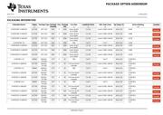
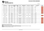
标记信息在P19P20P21
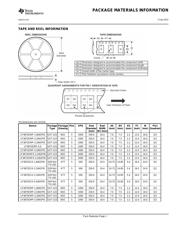
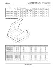
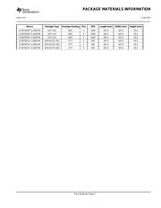
封装信息在P18P19P20P21P22P23P24
技术参数、封装参数在P4
应用领域在P1
电气规格在P5P6P15
导航目录
LP3875ES-3.3/NOPB数据手册
Page:
of 28 Go
若手册格式错乱,请下载阅览PDF原文件
LP3872
,
LP3875
SNVS227H –FEBRUARY 2003–REVISED JANUARY 2015
www.ti.com
Typical Application (continued)
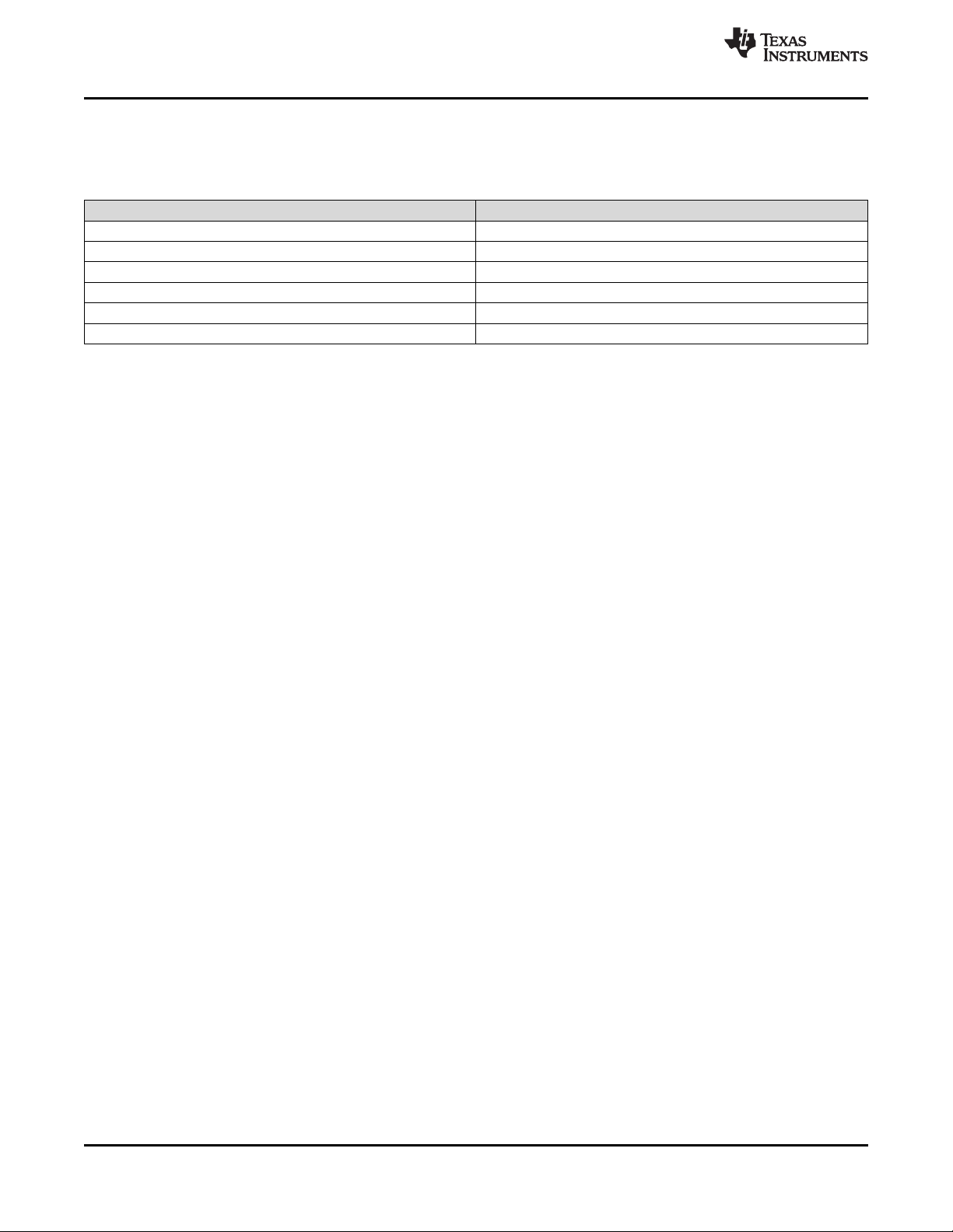
8.2.1 Design Requirements
Table 1. Design Parameters
DESIGN PARAMETER EXAMPLE VALUE
Input voltage range 2.5 V to 7 V
Output voltage 1.8 V
Output current 1.5 A
Output capacitor 10 µF
Input capacitor 10 µF
Output capacitor ESR range 100 mΩ to 4 Ω
8.2.2 Detailed Design Procedure
8.2.2.1 Power Dissipation and Device Operation
The permissible power dissipation for any package is a measure of the capability of the device to pass heat from
the power source, the junctions of the IC, to the ultimate heat sink, the ambient environment. Thus, the power
dissipation depends on the ambient temperature and the thermal resistance across the various interfaces
between the die junction and ambient air.
The maximum allowable power dissipation for the device in a given package can be calculated using Equation 1:
P
D-MAX
= ((T
J-MAX
– T
A
) / R
θJA
) (1)
The actual power being dissipated in the device can be represented by Equation 2:
P
D
= (V
IN
– V
OUT
) × I
OUT
(2)
Equation 1 and Equation 2 establish the relationship between the maximum power dissipation allowed due to
thermal consideration, the voltage drop across the device, and the continuous current capability of the device.
These two equations should be used to determine the optimum operating conditions for the device in the
application.
In applications where lower power dissipation (P
D
) and/or excellent package thermal resistance (R
θJA
) is present,
the maximum ambient temperature (T
A-MAX
) may be increased.
In applications where high power dissipation and/or poor package thermal resistance is present, the maximum
ambient temperature (T
A-MAX
) may have to be derated. T
A-MAX
is dependent on the maximum operating junction
temperature (T
J-MAX-OP
= 125°C), the maximum allowable power dissipation in the device package in the
application (P
D-MAX
), and the junction-to ambient thermal resistance of the part/package in the application (R
θJA
),
as given by Equation 3:
T
A-MAX
= (T
J-MAX-OP
– (R
θJA
× P
D-MAX
)) (3)
Alternately, if T
A-MAX
can not be derated, the P
D
value must be reduced. This can be accomplished by reducing
V
IN
in the V
IN
– V
OUT
term as long as the minimum V
IN
is met, or by reducing the I
OUT
term, or by some
combination of the two.
8.2.2.2 External Capacitors
Like any low-dropout regulator, external capacitors are required to assure stability. These capacitors must be
correctly selected for proper performance.
• Input Capacitor: An input capacitor of at least 10 µF is required. Ceramic, tantalum, or Electrolytic capacitors
may be used, and capacitance may be increased without limit.
• Output Capacitor: An output capacitor is required for loop stability. It must be located less than 1 cm from the
device and connected directly to the output and ground pins using traces which have no other currents
flowing through them (see Layout section).
The minimum value of output capacitance that can be used for stable full-load operation is 10 µF, but it may be
increased without limit. The output capacitor must have an equivalent series resistance (ESR) value as shown in
Figure 14. Tantalum capacitors are recommended for the output capacitor.
12 Submit Documentation Feedback Copyright © 2003–2015, Texas Instruments Incorporated
Product Folder Links: LP3872 LP3875
器件 Datasheet 文档搜索
AiEMA 数据库涵盖高达 72,405,303 个元件的数据手册,每天更新 5,000 多个 PDF 文件
