Datasheet 搜索 > 接口芯片 > TI(德州仪器) > DP83867IRRGZR 数据手册 > DP83867IRRGZR 开发手册 5/7 页
 器件3D模型
¥ 17.423
DP83867IRRGZR 开发手册 - TI(德州仪器)
制造商:
TI(德州仪器)
分类:
接口芯片
封装:
VQFN-48
描述:
具有工业级温度范围的耐用型千兆位以太网 PHY 收发器 48-VQFN -40 to 85
Pictures:
3D模型
符号图
焊盘图
引脚图
产品图
页面导航:
应用领域在P7
导航目录
DP83867IRRGZR数据手册
Page:
of 7 Go
若手册格式错乱,请下载阅览PDF原文件

www.ti.com
SFD Measurement Results
6 SFD Measurement Results
The end to end latency of a link can be measured by the delay from the transmit SFD on one device to the
receive SFD of a second device. For real-time systems and systems implementing the IEEE 1588
Precision Time Protocol, this measurement could be made by comparing the timestamps of the two SFDs.
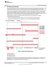
Start of Frame was measured using the configuration previously described in Section 4. The test setup
consisted of two DP83867 boards connected via a 1m cable. Transmit data was provided to the Device
under Test (DUT). Data received by the link partner was looped back to the link partner transmit pins via a
wiring harness. In this way, all four SFDs could be measured relative to one another.
In the test setup, the end to end latencies were measured using an oscilloscope. The latency
measurements were calculated as:
• DUT TX SFD to Partner RX SFD (shown as C1->C4 in the oscilloscope shots below)
• Partner TX SFD to DUT RX SFD (shown as C3->C2 in the oscilloscope shots below)
Figure 4. Start of Frame Measurement
Ch1: DUT TX SFD
Ch2: DUT RX SFD
Ch3: Partner TX SFD
Ch4: Partner RX SFD
Data taken for 100 consecutive links with oscilloscope configured for infinite persistence. Variation in the
repeatability of the SFDs would be indicated by multiple edges on the rising edges of the SFD pulses.
Note that there is no variation for the SFDs see Figure 4.
5
SNLA242–October 2015 How to Configure DP83867 Start of Frame Detect
Submit Documentation Feedback
Copyright © 2015, Texas Instruments Incorporated
器件 Datasheet 文档搜索
AiEMA 数据库涵盖高达 72,405,303 个元件的数据手册,每天更新 5,000 多个 PDF 文件
