Datasheet 搜索 > 实时时钟芯片 > Maxim Integrated(美信) > DS1340U-3+T&R 数据手册 > DS1340U-3+T&R 开发手册 1/16 页
 器件3D模型
¥ 18.37
DS1340U-3+T&R 开发手册 - Maxim Integrated(美信)
制造商:
Maxim Integrated(美信)
分类:
实时时钟芯片
封装:
TSSOP-8
描述:
实时时钟 I2C RTC w/Trickle Charger
Pictures:
3D模型
符号图
焊盘图
引脚图
产品图
页面导航:
电气规格在P5
导航目录
DS1340U-3+T&R数据手册
Page:
of 16 Go
若手册格式错乱,请下载阅览PDF原文件

Maxim > Design Support > Technical Documents > Application Notes > Real-Time Clocks > APP 95
Keywords: DS1307, DS1339, DS1340, 2-wire, serial interface, example code, sample code, example
program, sample program, timekeeping, real time clocks, RTCs
APPLICATION NOTE 95
Interfacing the DS1307 with an 8051-Compatible
Microcontroller
Mar 29, 2001
Abstract: This application note provides information on how to interface a DS1307 real-time clock (RTC)
to a microcontroller and provides some example code for accessing the part.
Introduction
The DS1307 Serial Real Time Clock, which incorporates a 2-wire serial interface, can be controlled
using an 8051-compatible microcontroller. The DS1307 in this example is connected directly to two of
the I/O ports on a DS5000 microcontroller and the 2-wire handshaking is handled by low-level drivers,
which are discussed in this application note.
DS1307 Description
The DS1307 Serial Real Time Clock is a low-power, full BCD clock/calendar plus 56 bytes of nonvolatile
SRAM. Address and data are transferred serially via the 2-wire bi-directional bus. The clock/calendar
provides seconds, minutes, hours, day, date, month, and year information. The end of the month date is
automatically adjusted for months with less than 31 days, including corrections for leap year. The clock
operates in either the 24-hour or 12-hour format with AM/PM indicator. The DS1307 has a built-in power
sense circuit which detects power failures and automatically switches to the battery supply.
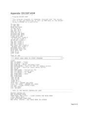
DS1307 Operation
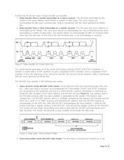
The DS1307 operates as a slave device on the serial bus. Access is obtained by implementing a START
condition and providing a device identification code followed by a register address. Subsequent registers
can be accessed sequentially until a STOP condition is executed. The START and STOP conditions are
generated using the low level drives, SEND_START and SEND_STOP found in the attached DS5000
code. Also the subroutines SEND_BYTE and READ_BYTE provide the 2-wire handshaking required for
writing and reading 8-bit words to and from the DS1307.
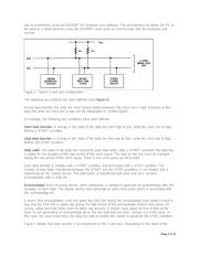
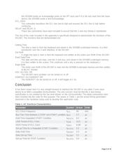
Hardware Configuration
The system is configured as shown in Figure 1. The DS1307 has the 2-wire bus connected to two I/O
port pins of the DS5000: SCL - P1.0, SDA - P1.1. The V
DD
voltage is 5V, R
P
= 5KΩ and the DS5000 is
using a 12-MHz crystal. The other peripheral device could be any other device that recognizes the 2-
wire protocol, such as the DS1621 Digital Thermometer and Thermostat. The interface with the D5000
Page 1 of 16
器件 Datasheet 文档搜索
AiEMA 数据库涵盖高达 72,405,303 个元件的数据手册,每天更新 5,000 多个 PDF 文件
