Datasheet 搜索 > 微控制器 > Microchip(微芯) > DSPIC33FJ128MC706A-E/PT 数据手册 > DSPIC33FJ128MC706A-E/PT 开发手册 3/18 页
 器件3D模型
¥ 64.482
DSPIC33FJ128MC706A-E/PT 开发手册 - Microchip(微芯)
制造商:
Microchip(微芯)
分类:
微控制器
封装:
TQFP-64
描述:
16位 DSC 带128 KB闪存 采用64引脚TQFP封装
Pictures:
3D模型
符号图
焊盘图
引脚图
产品图
页面导航:
原理图在P2P5
导航目录
DSPIC33FJ128MC706A-E/PT数据手册
Page:
of 18 Go
若手册格式错乱,请下载阅览PDF原文件
© 2005 Microchip Technology Inc. DS01017A-page 3
SINUSOIDAL CONTROL OF PMSM MOTORS WITH DSPIC30F DSC
PROGRAMMING THE dsPIC30F2010
WITH THE dsPICDEM™ MCLV
DEVELOPMENT BOARD
The dsPICDEM MCLV development board allows you
to program the dsPIC30F2010 in-circuit. To program
the part, you must set DIP switch S4 to the PRGM posi-
tion. When programming is complete, you must set the
DIP switch to the DEBUG position to execute the code.
If the IDC2 is connected to the PICDEM™ MCLV devel-
opment board as a debugger, the connector at J6
should be attached. If you use MPLAB
®
ICD 2 as a
debugger, the RJ11 cable should be connected to the
board (J6). If you use MPLAB ICD 2 as a programmer
only, the RJ11 cable should be connected for program-
ming the part and unplugged for normal program exe-
cution.
The following configuration allows the application to
work on a PICDEM™ MCLV development board:
Other settings can be enabled or disabled as needed,
or modified in the application.
BACKGROUND
Many consumer and industrial applications use the
BLDC motor because of its compact size, controllability
and high efficiency. Increasingly, it is used in automo-
tive applications as part of a strategy to eliminate belts
and hydraulic systems, to increase functionality and to
improve fuel economy. In high-performance applica-
tions, such as machine tools and low noise fan
applications, the production of smooth torque is crucial.
The main disadvantage of BLDC motors, when low
torque ripple and quieter operation are required, is the
non-sinusoidal distribution of the stator windings.
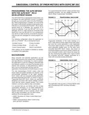
BLDC motors with non-sinusoidal winding distribution
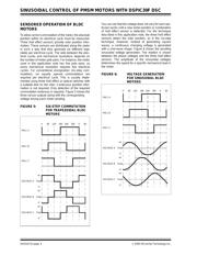
generate trapezoidal back-EMF, as shown in Figure 3.
Trapezoidal Back-EMF BLDC motors are specifically
designed to be driven with square voltages synchro-
nized with the motor’s angular position. This control
method is commonly called six-step commutation.
It is assumed that you are familiar with the six-step
commutation technique, so no further elaboration is
offered in this application note. However, for more
detailed information on how to operate a BLDC motor
with six-step commutation, you can refer to these
additional Microchip application notes:
• AN857 “Brushless DC Motor Control Made Easy”
(DS00857)
• AN957 “Sensored BLDC Motor Control Using
dsPIC30F2010” (DS00957)
For a good introduction to BLDC motors and their basic
operating principles, see also AN885 “Brushless DC
(BLDC) Motor Fundamentals” (DS00885) .
FIGURE 3: TRAPESOIDAL BACK-EMF
Trapezoidal distribution of the motor windings of a
BLDC motor leads to torque ripple during motor opera-
tion since the current generation is also trapezoidal.
This torque ripple produces a small speed oscillation,
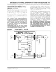
which generates audible noise. On the other hand,
sinusoidal Back-EMF BLDC motors, also known as
Permanent Magnet Synchronous Motors (PMSM) pro-
duce sinusoidal currents, which reduce the torque rip-
ple, thus minimizing the audible noise. Figure 4 shows
the sinusoidal back-EMF voltages generated by a
motor with sinusoidal winding distribution.
FIGURE 4: SINUSOIDAL BACK-EMF
This application note assumes a 3-Phase PMSM motor
with sinusoidal back-EMF and three Hall effect
sensors.
Oscillator Source: Primary Oscillator
Primary Oscillator Mode: XT w/PLL 16x
Comm Channel Select: EMUC2 and EMUD2
0060 60120 180 240 300
Phase A
Phase B
Phase C
0060 60120 180 240 300
Phase A
Phase B
Phase C
器件 Datasheet 文档搜索
AiEMA 数据库涵盖高达 72,405,303 个元件的数据手册,每天更新 5,000 多个 PDF 文件
