Datasheet 搜索 > ON Semiconductor(安森美) > FSUSB42UMX-SN00404 数据手册 > FSUSB42UMX-SN00404 开发手册 3/5 页
 器件3D模型
¥ 1.312
FSUSB42UMX-SN00404 开发手册 - ON Semiconductor(安森美)
制造商:
ON Semiconductor(安森美)
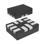
封装:
UQFN-10
Pictures:
3D模型
符号图
焊盘图
引脚图
产品图
页面导航:
型号编码规则在P5
标记信息在P1P5

导航目录
FSUSB42UMX-SN00404数据手册
Page:
of 5 Go
若手册格式错乱,请下载阅览PDF原文件

AN-9073 APPLICATION NOTE
© 2007 Fairchild Semiconductor Corporation www.fairchildsemi.com
Rev. 1.0.0 • 5/11/10 2
Guidelines for Successful USB Switch Board Routing
1. USB switches should be placed as close to the
USB controller as possible. There should be no
more than 1 inch between the controller and USB
switch. For best results, this distance should be
kept to less than ¼ of the transmission electrical
length (<18mm). The distance from USB switch
to USB connector should be <1 inch to minimize
system signal loss.
2. The D+D- lines should be routed using an
impedance calculator to ensure they achieve 90Ω
differential impedance. Shorter traces usually
mean less loss, less chance of picking up stray
noise, and may radiate less EMI.
3. Select the best transmission line for the
application. In the case of a densely populated
board (such as a laptop computer), an edge-
coupled differential stripline would be the right
choice.
4. Terminations are critically important in a
transmission line and differ among driver and
receiver topologies. Some applications require a
source or “back” termination, some require
receiver or “far end” terminations, and some
require both. In all cases, the termination
components must be placed as close as possible to
their respective pins. For this reason, many high-
speed circuits have on-chip terminations to aid in
the process.
5. Minimize the use of vias and keep high-speed lines
on certain planes in the stackup. Vias are an
interruption in the impedance of the transmission
line and should be avoided. Choosing a stripline
scheme generally forces the use of at least two vias,
one on each end to get the signal to and from the
surface. Moving to another plane for the
convenience of the route should be avoided.
6. If lines must be crossed in a stripline stackup,
cross orthogonally to avoid noise coupling
(traces running in parallel couple).
7. When space allows, GND copper should be run
adjacent to the transmission lines to help isolate
from noise sources. The distance from the
transmission line to the GND should be
considered in the impedance calculation.
Anything (GND, power, components, etc.) close
to the transmission line could alter the impedance
of the transmission line and create a
discontinuity.
8. When routing high-speed lines, be aware of trace
length. This is especially important for
differential traces and parallel data where timing
is critical. It is not uncommon to require lengths
to be matched to within a millimeter.
9. Avoid sharp bends in PCB traces; a chamfer or
rounding is generally preferred.
10. When decoupling power pins, the choice of a
low-ESR capacitor placed at or very near the
power pin is critical. Where sensitive analog
circuits are being powered, a tuned PI filter
should be used to negate the effects of switching
power supplies and other noise sources.
器件 Datasheet 文档搜索
AiEMA 数据库涵盖高达 72,405,303 个元件的数据手册,每天更新 5,000 多个 PDF 文件
