Datasheet 搜索 > TI(德州仪器) > LM43603DSUT 数据手册 > LM43603DSUT 开发手册 1/11 页

¥ 40.03
LM43603DSUT 开发手册 - TI(德州仪器)
制造商:
TI(德州仪器)
封装:
VSON EP-16
描述:
3.5V 至 36V、3A 同步降压转换器 16-SON -40 to 125
Pictures:
3D模型
符号图
焊盘图
引脚图
产品图
页面导航:
引脚图在P2P8Hot
原理图在P3P4
应用领域在P11
导航目录
LM43603DSUT数据手册
Page:
of 11 Go
若手册格式错乱,请下载阅览PDF原文件

Application Report
SNVA721A–September 2014–Revised September 2014
Low Radiated EMI Layout Made SIMPLE with LM4360x and
LM4600x
YangZhang
ABSTRACT
Printed Circuit Board (PCB) layout for Switched Mode Power Supplies (SMPS) is critical to achieve proper
converter operation, good thermal performance, and excellent radiated EMI performance. Optimized board
layout for low radiated EMI is made very simple by the package and pin arrangement of the SIMPLE
SWITCHER® Synchronous Buck Converter family LM4360x and LM4600x.
Contents
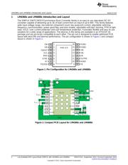
1 LM4360x and LM4600x Introduction and Layout........................................................................ 2
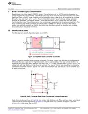
2 Buck Converter Layout Considerations................................................................................... 3
2.1 Identify critical paths................................................................................................ 3
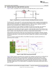
2.2 Minimize High Power High di/dt Path Loop Area............................................................... 4
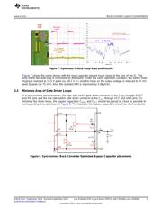
2.3 Minimize Area of Gate Driver Loops ............................................................................. 5
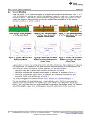
2.4 Ground Shielding ................................................................................................... 6
2.5 Protect Sensitive Nodes ........................................................................................... 7
3 Benefits of the LM4360x and LM4600x Pin Configuration ............................................................. 8
4 Radiated EMI result of the LM4360x and LM4600x..................................................................... 9
List of Figures
1 Pin Configuration for LM4360x and LM4600x ........................................................................... 2
2 Compact PCB Layout for LM4360x and LM4600x ...................................................................... 2
3 Simplified Buck Converter Schematic..................................................................................... 3
4 Buck Converter Gate Drive Circuits with Bypass Capacitors .......................................................... 3
5 Simplified Buck Converter Schematic Illustrating Minimized Loop Area ............................................. 4
6 Large Critical Loop Area and Results..................................................................................... 4
7 Optimized Critical Loop Area and Results................................................................................ 5
8 Synchronous Buck Converter Optimized Bypass Capacitor placements ............................................ 5
9 Cross Section Illustration of the Two Layer Board ...................................................................... 6
10 Cross Section Illustration of the Four Layer Board with Unbroken Ground Planes................................. 6
11 Cross Section Illustration of the Four Layer Board with Broken Ground Planes.................................... 6
12 Radiated EMI Result from the Two Layer Board ........................................................................ 6
13 Radiated EMI Result from the Four Layer Board with Unbroken Ground Planes................................... 6
14 Radiated EMI Result from the Four Layer Board with Broken Ground Planes...................................... 6
15 Avoid Long Traces to the FB Node........................................................................................ 7
16 Use Short and Thin Traces at the FB Node.............................................................................. 7
17 Benefits of LM4360x and LM4600x Pin Configuration.................................................................. 8
18 LM43603 Radiated EMI Curve............................................................................................. 9
19 LM46002 Radiated EMI Curve............................................................................................. 9
20 LM43602 Radiated EMI Curve............................................................................................. 9
21 LM46001 Radiated EMI Curve............................................................................................. 9
1
SNVA721A–September 2014–Revised September 2014 Low Radiated EMI Layout Made SIMPLE with LM4360x and LM4600x
Submit Documentation Feedback
Copyright © 2014, Texas Instruments Incorporated
器件 Datasheet 文档搜索
AiEMA 数据库涵盖高达 72,405,303 个元件的数据手册,每天更新 5,000 多个 PDF 文件
