Datasheet 搜索 > 电源管理 > Maxim Integrated(美信) > MAX4940CTN+ 数据手册 > MAX4940CTN+ 开发手册 1/14 页
 器件3D模型
¥ 405.172
MAX4940CTN+ 开发手册 - Maxim Integrated(美信)
制造商:
Maxim Integrated(美信)
分类:
电源管理
封装:
TQFN-56
描述:
高压数字脉冲发生器, 2.3 V至6 V, TQFN-56
Pictures:
3D模型
符号图
焊盘图
引脚图
产品图
页面导航:
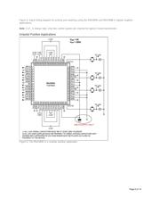
典型应用电路图在P4
应用领域在P3P6P8
导航目录
MAX4940CTN+数据手册
Page:
of 14 Go
若手册格式错乱,请下载阅览PDF原文件
Maxim > Design Support > Technical Documents > Application Notes > Amplifier and Comparator Circuits > APP 5131
Maxim > Design Support > Technical Documents > Application Notes > Analog Switches and Multiplexers > APP 5131
Keywords: industrial, ultrasound, NDT, flow meter, sonar, probe, system channels, high voltage, AFE, pulser, switch,
unipolar, bipolar, low frequency, high frequency probe, HV
APPLICATION NOTE 5131
Maxim Addresses High-Voltage Needs in Industrial
Ultrasound Applications
By: Luigi Franchini
Aug 26, 2011
Abstract:
Most ICs
for ultrasound transmission available today are aimed to cover medical applications and do not
necessarily fit the needs for industrial applications. Industrial applications such as nondestructive tests (NDTs), flow
meters, and sonar often have different requirements for voltage capability, current capability, and frequency. Thanks to
their great flexibility, Maxim's high-voltage (HV) products can be used in a broad range of applications. This article
presents a variety of applications for the MAX4940 quad HV digital pulser and the MAX4968 HV multiplexer (mux).
Table of Contents
Overview
The MAX4940 HV Digital Pulser
The MAX4968 HV Analog Switch
Supported Applications
Bipolar
Unipolar Positive
Unipolar Negative
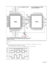
Doubling the Voltage Capability with BTL Configurations
Increasing the Current Capability with Parallelization
Low- and High-Frequency Operations
Low-Frequency Operation (< 1MHz)
High-Frequency Operation (> 20MHz)
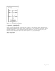
Overview
The MAX4940 HV Digital Pulser
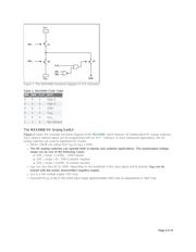
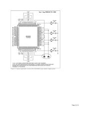
Figure 1 shows the essential functional diagram of the MAX4940, a device that features 4 channels for high-voltage
(HV) digital pulsing. (Only 1 out of the 4 channels is displayed in the diagram.)
S1 and S2 switches (connected to V
PP
_ and V
NN
_, respectively) feature 200V voltage capability and 2A current
capability.
S3 switch (called "clamp" in the data sheet) features 200V voltage and 1A current capability.
The digital pulser can operate in both bipolar and unipolar applications. In other words, all of the
following cases are supported:
[V
PP
, V
NN
] = [+100V, -100V] bipolar
[V
PP
, V
NN
] = [0, -200V] unipolar negative
[V
PP
, V
NN
] = [+200V, 0] unipolar positive
INP_ and INN_ control S1 and S2, respectively.
INC_ controls S3 (clamp), but it is conditioned by S1 and S2. In most applications, INC_ does not need to be
driven. You can always keep it high and drive INP_ and INC_ only. In doing so, S3 is activated every time both
S1 and S2 are off.
Page 1 of 14
器件 Datasheet 文档搜索
AiEMA 数据库涵盖高达 72,405,303 个元件的数据手册,每天更新 5,000 多个 PDF 文件
