Datasheet 搜索 > 微控制器 > Microchip(微芯) > PIC18F4520-I/P 数据手册 > PIC18F4520-I/P 开发手册 1/32 页
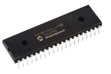
 器件3D模型
¥ 61.639
PIC18F4520-I/P 开发手册 - Microchip(微芯)
制造商:
Microchip(微芯)
分类:
微控制器
封装:
DIP-40
描述:
PIC18F2420/2520/4420/4520 8 位微控制器Microchip 的 PIC18F 微控制器是 Microchip 产品线中功能最强大的 8 位设备。 该系列包含的 CAN、LIN 和以太网功能是完整系列外围设备的一部分,可满足嵌入式应用和版本的需求,采用 XLP(极低功耗)技术,用于功耗为关键考量的应用。 PIC18F2420/2520/4420/4520 系列微控制器基于 Microchip 的 PIC18 体系结构,提供 31 级 硬件堆栈和 75 指令。 这些 MCU 提供高达 10 个 MIPS、多达 64 kb 的程序存储器、多达 3896 kb 的 RAM。 板载可配置振荡器。### 微控制器功能40 MHz 最大 CPU 速度 75 指令 - 通过扩展指令集支持 83 指令 31 级硬件堆栈 可配置内部振荡器 - 可选频率范围 8 mHz 至 31 kHz 25 个输入/输出引脚 - PIC18F2420/2520 型号 36 个输入/输出引脚 - PIC18F4420/4520 型号 nanoWatt 技术 通电重置 (POR) 通电计时器 (PWRT) 振荡器启动计时器 (OST) 掉电重置 (BOR) 延长监控计时器 (WDT) 高电压/低电压检测 (HLVD) 模块 低电压编程 (LVP) 在线串行编程 (ICSP) 在线调试 (ICD) ### 外设10 位模拟到数字转换器 (ADC) - PIC18F2420/2520 型号 10 通道;PIC18F4420/4520 13 通道 一个增强型采集、比较、PWM 模块 - 仅 PIC18F4420/4520 型号 采集、比较、PWM 模块 - PIC18F2420/2520 型号 x 2、PIC18F4420/4520 型号 x 1 两个比较器 一个 8 位计时器 三个 16 位计时器 主同步串行端口 (MSSP) 模块,带有 SPI 和 I2C 增强型可寻址通用同步异步接收器发送器 (EUSART) ### PIC18 微控制器展开
Pictures:
3D模型
符号图
焊盘图
引脚图
产品图
页面导航:
原理图在P2
应用领域在P10
导航目录
PIC18F4520-I/P数据手册
Page:
of 32 Go
若手册格式错乱,请下载阅览PDF原文件

2003 Microchip Technology Inc. DS00247A-page 1
AN247
INTRODUCTION
Among the many features built into Microchip’s
Enhanced FLASH Microcontroller devices is the capa-
bility of the program memory to self-program. This very
useful feature has been deliberately included to give
the user the ability to perform bootloading operations.
Devices like the PIC18F458 are designed with a desig-
nated “boot block”, a small section of protectable pro-
gram memory allocated specifically for bootload
firmware.
This application note demonstrates a simple boot-
loader implementation for the PIC18F families of micro-
controllers with a CAN module. The goals of this
implementation are to stress maximum performance
and functionality, while requiring a minimum of code
space. For users developing CAN enabled systems, it
provides a low level framework that can be used with
higher level network protocols to develop more
complex and custom-tailored systems.
CONSIDERATIONS FOR FIELD
PROGRAMMING OVER THE CAN BUS
The combination of FLASH technology and robust net-
work communication capability in a single device
makes over-the-network programmability a very desir-
able option. However, this makes bootloading on a
CAN bus network a very different challenge from more
typical uses, such as using a bootloader to program a
single FLASH device in isolation. Let’s consider some
of the key issues in over-the-network programming.
Single or Group Programming
Providing bootloading capability over a CAN bus net-
work takes some forethought. For example, a system
with a number of nodes may have identical firmware in
several nodes. Since every node on a CAN bus can
see all passing data, it may be more efficient to
program these identical nodes in a single pass.
However, in other cases where a node or many nodes
are unique, it may only be necessary to open
peer-to-peer communications to program the device.
This can be the simplest programming system,
because the programming source could contain all the
intelligence and freely manipulate the target memory.
The drawback to this is a lack of efficiency, as directly
manipulating the target memory and manually verifying
data takes significant time on the CAN bus.
To make the operation more efficient, the programming
target could be given some intelligence, like self-
verification. This would make communications
unidirectional, essentially cutting the time on the CAN
bus in half.
Overall, the best savings is to design all the nodes in
the system with similar, modular firmware. Each node
could then use only those modules required for its task,
but the entire group of nodes could be updated simul-
taneously. The sacrifice here is program memory over-
head, since some nodes may have resident firmware
that is not used.
Programming a Running System
An interesting situation is bootloading in an active and
functioning system. In this instance, one or more of the
nodes are taken off-line to update their firmware, yet
the functionality of the entire system is not completely
disabled. This, of course, requires that the target node
or nodes have some functional independence from
other parts of the networked system.
There are priority issues to contend with when pro-
gramming in an active system. For example, what pri-
ority can be given to the bootloader without affecting
the critical communications in the system? If higher pri-
ority is given to nodes running the bootloader than
other nodes running their normal application, then it
may take time for data to be received when data is
being streamed to the programming target. Thus, criti-
cal systems that require relatively low latency for data
transmission or reception may fail to function as
expected. In the opposite situation, assigning the pro-
gramming target with a priority that is too low could lead
to extremely long programming times, simply because
the programming source and target are continually
waiting for an IDLE bus to pass data.
In an active network, planning is necessary to provide
sufficient bus time for programming. One solution is
simply to give relatively high priority to bootloader pro-
gramming operations, then design the programming
source to “inject” time for other applications while
streaming data on the CAN bus. Thus, bus time is
always available and controlled by the programming
source.
Author: Ross M. Fosler
Microchip Technology Inc.
A CAN Bootloader for PIC18F CAN Microcontrollers
器件 Datasheet 文档搜索
AiEMA 数据库涵盖高达 72,405,303 个元件的数据手册,每天更新 5,000 多个 PDF 文件
