Datasheet 搜索 > DC/DC转换器 > ON Semiconductor(安森美) > UC3845BVD1R2G 数据手册 > UC3845BVD1R2G 开发手册 1/8 页
 器件3D模型
¥ 2.416
UC3845BVD1R2G 开发手册 - ON Semiconductor(安森美)
制造商:
ON Semiconductor(安森美)
分类:
DC/DC转换器
封装:
SOIC-8
描述:
UC3845B 系列 36 V 275 kHz 高性能 电流模式 控制器 - SOIC-8
Pictures:
3D模型
符号图
焊盘图
引脚图
产品图
页面导航:
原理图在P1P4
型号编码规则在P8
技术参数、封装参数在P2
导航目录
UC3845BVD1R2G数据手册
Page:
of 8 Go
若手册格式错乱,请下载阅览PDF原文件
© Semiconductor Components Industries, LLC, 2005
August, 2005 − Rev. 1
1 Publication Order Number:
AND8039/D
AND8039/D
The One−Transistor
Forward Converter
Introduction
The one−transistor forward converter is the most
elementary form of transformer−isolated buck converter. It
is typically used in off−line applications in the
100 W − 300 W region. This application note illustrates the
approach one would take to design a high DC input voltage,
one−transistor forward converter. With additional
modifications, it could be made work as a 110 VAC off−line
power supply.
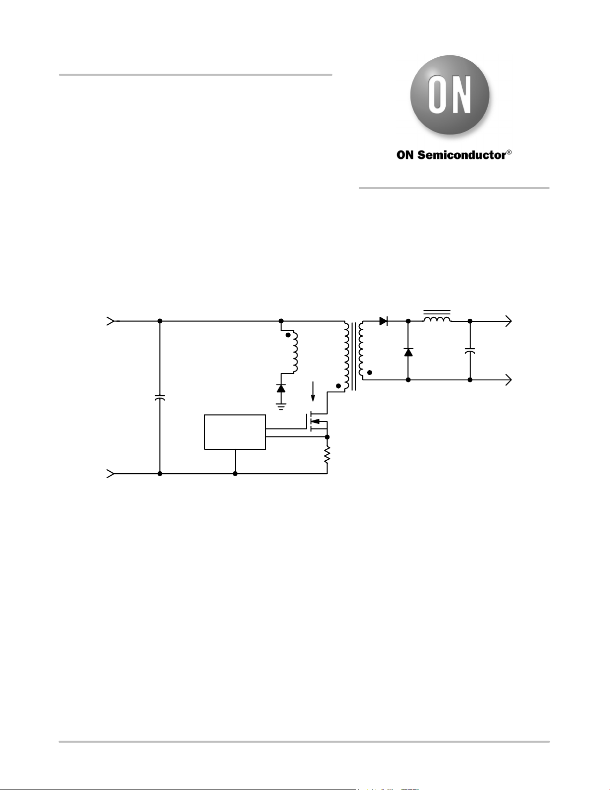
Description of Operation
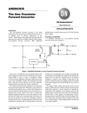
A simplified schematic of a one−transistor forward
converter can be seen in Figure 1.
CONTROL
RESET
WINDING
C
IN
+
+
+
V
SW
−
I
SW
+V
IN
GND
D1
D2
L
O
+V
OUT
GND
C
OUT
Figure 1. Simplified Schematic of a One Transistor Forward Converter
One can see a transformer has been placed between the
input voltage and a buck converter output stage. The power
switch (SW) is used to create a rectangular voltage
waveform whose amplitude is the input voltage and its duty
cycle is the controllable variable. The transformer provides
both a step−up or down function and a safety dielectric
isolation between the input line and the output load.
The major restriction of this topology is the maximum
duty cycle must be about 50%. Whenever a core is driven in
a unidirectional fashion, that is, current only being driven
from one direction into the primary, the core must be reset.
Magnetization energy which serves only to reorient the
magnetic domains within the core must be emptied, or else
the core will “walk−up” to saturation after a few cycles. To
do this, one needs to reset the core. Resetting is done by
drawing current from a winding during the period when the
transformer is unloaded, that is, when the power switch and
rectifiers are not conducting. Any winding can provide the
reset function, but the higher the voltage on the winding, the
quicker the core will reset. Typically, this is the primary
winding or a separate reset winding of equal turns to the
primary. Current from the reset winding can then be returned
to the input capacitor and reused during the next cycle of
operation.
The typical switch voltage and current can be seen in
Figure 2. When the power switch is ON, the switch sees the
output filter inductor’s current reflected by through the
transformer. The amplitude of the primary current is the
output rectifier current times turns ratio of the transformer
(N1/N2) plus a small amount of magnetization current.
During the power switch OFF time, the switch voltage “flys”
up to about twice the input voltage. During this time, the
reset winding begins to output magnetization current back
to the input capacitor.
APPLICATION NOTE
http://onsemi.com
器件 Datasheet 文档搜索
AiEMA 数据库涵盖高达 72,405,303 个元件的数据手册,每天更新 5,000 多个 PDF 文件
