Datasheet 搜索 > PANJIT Touch Screens > 1N5349 数据手册 > 1N5349 数据手册 1/7 页


¥ 0
1N5349 数据手册 - PANJIT Touch Screens
制造商:
PANJIT Touch Screens
封装:
DO-201AE
Pictures:
3D模型
符号图
焊盘图
引脚图
产品图
页面导航:
导航目录
1N5349数据手册
Page:
of 7 Go
若手册格式错乱,请下载阅览PDF原文件
© Semiconductor Components Industries, LLC, 2013
November, 2013 − Rev. 15
1 Publication Order Number:
1N5333B/D
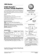
1N53 Series
5 Watt Surmetict
40 Zener Voltage Regulators
This is a complete series of 5 Watt Zener diodes with tight limits and
better operating characteristics that reflect the superior capabilities of
silicon−oxide passivated junctions. All this in an axial lead,
transfer−molded plastic package that offers protection in all common
environmental conditions.
Features
• Zener Voltage Range − 3.3 V to 200 V
• ESD Rating of Class 3 (>16 kV) per Human Body Model
• Surge Rating of up to 180 W @ 8.3 ms
• Maximum Limits Guaranteed on up to Six Electrical Parameters
• Pb−Free Packages are Available*
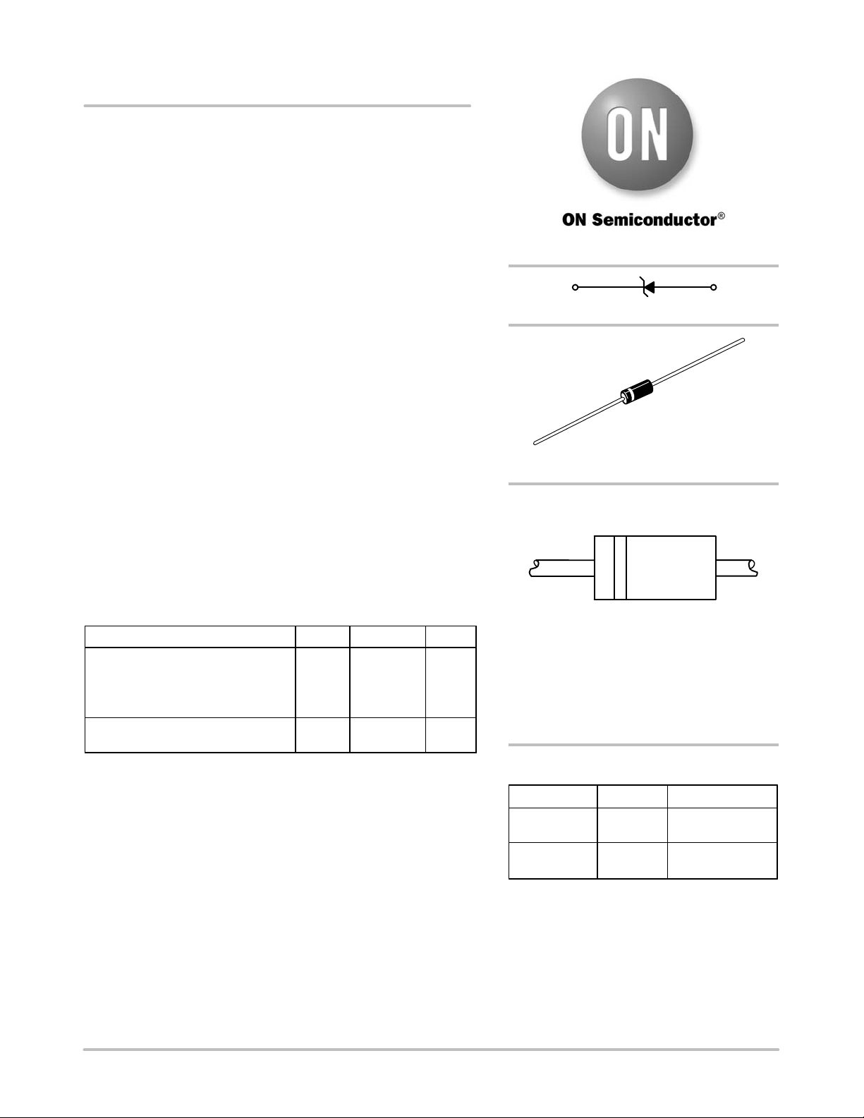
Mechanical Characteristics
CASE:
Void free, transfer−molded, thermosetting plastic
FINISH: All external surfaces are corrosion resistant and leads are
readily solderable
MAXIMUM LEAD TEMPERATURE FOR SOLDERING PURPOSES:
260°C, 1/16 in. from the case for 10 seconds
POLARITY: Cathode indicated by polarity band
MOUNTING POSITION: Any
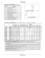
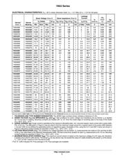
MAXIMUM RATINGS
Rating Symbol Value Unit
Max. Steady State Power Dissipation
@ T
L
= 25°C, Lead Length = 3/8 in
Derate above 25°C
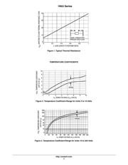
Junction−to−Lead Thermal Resistance
P
D
q
JL
5
40
25
W
mW/°C
°C/W
Operating and Storage
Temperature Range
T
J
, T
stg
−65 to +200
(Note 1)
°C
Stresses exceeding Maximum Ratings may damage the device. Maximum
Ratings are stress ratings only. Functional operation above the Recommended
Operating Conditions is not implied. Extended exposure to stresses above the
Recommended Operating Conditions may affect device reliability.
1. Max operating temperature for DC conditions is 150°C, but not to exceed
200°C for pulsed conditions with low duty cycle or non−repetitive.
*For additional information on our Pb−Free strategy and soldering details, please
download the ON Semiconductor Soldering and Mounting Techniques
Reference Manual, SOLDERRM/D.
http://onsemi.com
AXIAL LEAD
CASE 017AA
PLASTIC
Cathode Anode
MARKING DIAGRAM
A = Assembly Location
1N53xxB = Device Number
(Refer to Tables on Pages 3 & 4)
YY = Year
WW = Work Week
G =Pb−Free Package
A
1N
53xxB
YYWWG
G
Device Package Shipping
†
ORDERING INFORMATION
†For information on tape and reel specifications,
including part orientation and tape sizes, please
refer to our Tape and Reel Packaging Specifications
Brochure, BRD8011/D.
1N53xxB, G Axial Lead
(Pb−Free)
1000 Units/Box
1N53xxBRL, G Axial Lead
(Pb−Free)
4000/Tape & Reel
(Note: Microdot may be in either location)
器件 Datasheet 文档搜索
AiEMA 数据库涵盖高达 72,405,303 个元件的数据手册,每天更新 5,000 多个 PDF 文件
