Datasheet 搜索 > 轻触开关、轻推开关 > Bourns J.W. Miller(伯恩斯) > 7914G-1-032E 数据手册 > 7914G-1-032E 数据手册 1/1 页

¥ 3.045
7914G-1-032E 数据手册 - Bourns J.W. Miller(伯恩斯)
制造商:
Bourns J.W. Miller(伯恩斯)
分类:
轻触开关、轻推开关
封装:
SMD
描述:
4毫米SMD和通孔密封按键开关 4 mm SMD & Through-hole Sealed Key Switch
Pictures:
3D模型
符号图
焊盘图
引脚图
产品图
7914G-1-032E数据手册
Page:
of 1 Go
若手册格式错乱,请下载阅览PDF原文件
5.00
(.197)
0.20 ± 0.10
(.008 ± .004)
2
1
2
1
DIA.
4.50
(.177)
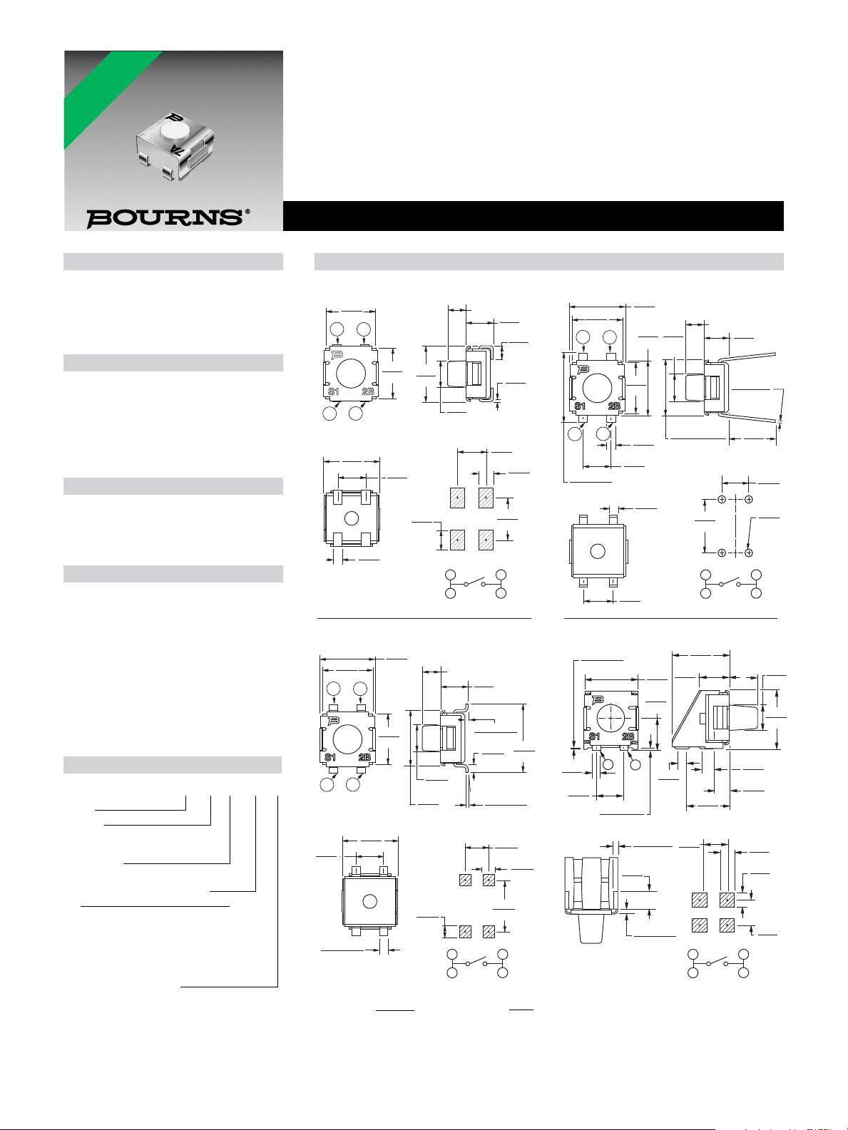
7914H
Through-hole
0.80
(.031)
RECOMMENDED PCB LAYOUT
2.54
(.100)
2 PLCS.
2.54
(.100)
2 PLCS.
2.54
(.100)
TYP.
0.76
(.030)
TYP.
0.76
(.030)
6.20 ± 0.10
(.244 ± .004)
5.00 +0.10/-0.15
(.197 +.004/-.006)
5.00
(.197)
4.50
(.177)
5.00
(.197)
2.39
(.094)
DIA.
2.17
(.085)
4.00
(.157)
TYP.
TYP.
0.76
(.030)
2
1
2
1
4.50
(.177)
2.54
(.100)
1.23
(.048)
0.20
(.008)
7914J
J-Hook
2.39
(.094)
DIA.
RECOMMENDED PCB LAYOUT
TYP.
1.78
(.070)
TYP.
2.54
(.100)
1.27
(.050)
3.81
(.150)
4.50
(.177)
5.00
(.197)
L
2.54
(.100)
5.00
(.197)
7914S
Right Angle
RECOMMENDED PCB LAYOUT
1
2
2.54
(.100)
1.3
TYP.
(.051)
2.33
(.092)
1.25
TYP.
(.049)
5.00
(.197)
0.2
± 0.13
(.008 ± .005)
0.13 ± 0.05
(.005 ± .002)
5.18
(.204)
2.75
(.108)
0.76
(.030)
0.89
(.035)
0.78
(.031)
1.5
(.059)
DIA.
L
3.89
(.153)
5.44
(.214)
2.38
(.094)
2.54
(.100)
2.86
(.113)
TYP.
2
1
2
1
4.50
(.177)
4.50
(.177)
2.54
(.100)
0.60
(.024)
±5° TYP.
7914G
Gull Wing
2.54
(.100)
2.39
(.094)
DIA.
TYP.
2.54
(.100)
1.27
(.050)
RECOMMENDED PCB LAYOUT
TYP.
1.27
(.050)
0.76 ± 0.10
(.030 ± .004)
TYP.
5.50
(.216)
5.00
(.197)
6.20
(.244)
4.93
(.194)
0.28 ± 0.20
(.011 ± .008)
0.20 ± 0.08
(.008 ± .003)
5.00
(.197)
0.48 ± 0.2
(.019 ± .008)
1.68
(.066)
0.38 ± 0.2
(.015 ± .008)
1
2
2
1
SPST N.O.
RECOMMENDED POLARITY
-
-
+
+
1
2
2
1
SPST N.O.
RECOMMENDED POLARITY
-
-
+
+
1
2
2
1
SPST N.O.
RECOMMENDED POLARITY
-
-
+
+
1
2
2
1
SPST N.O.
RECOMMENDED POLARITY
-
-
+
+
L
L
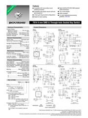
Features
■ Compatible with most surface mount
soldering processes
■ Compatible with popular vacuum pick-and
place equipment
■ J-hook, gull-wing & pinned confi gurations
■ Sealed for board washing
■ Meets EIA/EIAJ/IPC/VRCI SMD standard
outline dimensions
■ Top or side actuated
■ RoHS compliant*
■ For switch applications/processing
guidelines, click here
7914 4 mm SMD & Through-hole Sealed Key Switch
*RoHS Directive 2002/95/EC Jan. 27, 2003 including annex and RoHS Recast 2011/65/EU June 8, 2011.
†“Fluorinert” is a registered trademark of 3M Co.
Specifi cations are subject to change without notice.
The device characteristics and parameters in this data sheet can and do vary in different applications and actual device performance may vary over time.
Users should verify actual device performance in their specifi c applications.
Electrical Characteristics
Contact Rating
Maximum Current ..............100 mA max.
Maximum Voltage ............................16 V
Contact Resistance ..... 100 milliohms max.
Insulation Resistance .. 100 megohms min.
Dielectric Strength ........................250 VAC
General Characteristics
Switch Type .........................Normally open
Operating Temperature Range
....................................-55 °C to +125 °C
Storage Temperature Range
....................................-55 °C to +125 °C
Seal Test ...........................85 °C Fluorinert
†
Vibration ............................................. 20 G
Shock................................................ 100 G
Mechanical Characteristics
Actuator Force .........................300 ± 100 g
Pushover Strength (S Style)
...........................0.9 kilograms minimum
Cycle life, loaded ..........100,000 actuations
Contact resistance ....... 100 milliohms max.
Physical Characteristics
Cover Material .....................Stainless steel
Base Material....... Thermoplastic, UL94V-0
Terminal Material ... Copper alloy gold plated
Dome Material .. Stainless steel silver plated
Actuator Material ............ High temperature
silicon rubber
Marking ...................... Manufacturer’s code
and date code
Packaging Options
J & G ................... 500 pcs./reel (MSL-1);
50 pcs./tube
S........................... 200 pcs./reel (MSL-1)
H ......................................... 50 pcs./tube
Product Dimensions
How to Order
7914 J - 1 - 000 E
Model
Terminal
J = J-Hook H = Through-hole
G = Gull Wing S = Right Angle
Switch Type
1 = N.O. Au Contacts
Product Code for Button Height
“L” (For All Styles) from Top of Lid
000 = 1.65 mm
024 = 0.08 mm (Flush)
032 = 0.89 mm
050 = 2.67 mm (available in tube pack only
for J, G & H Styles, tape &
reel only for S Style)
Packaging Code (MSL-1)
Blank = Tube (for J, G & H Styles)
E = Plastic Embossed Tape & Reel (for J, G
& S Styles)
Note: S Style is only available in tape and
reel.
DIMENSIONS:
MM
(INCHES)
TOLERANCES:
±0.3
(.012)
EXCEPT WHERE NOTED.
*RoHS COMPLIANT
器件 Datasheet 文档搜索
AiEMA 数据库涵盖高达 72,405,303 个元件的数据手册,每天更新 5,000 多个 PDF 文件
