Datasheet 搜索 > EIC > 80SQ045 数据手册 > 80SQ045 数据手册 1/4 页


¥ 0
80SQ045 数据手册 - EIC
制造商:
EIC
Pictures:
3D模型
符号图
焊盘图
引脚图
产品图
页面导航:
导航目录
80SQ045数据手册
Page:
of 4 Go
若手册格式错乱,请下载阅览PDF原文件
© Semiconductor Components Industries, LLC, 2006
May, 2006 − Rev. 3
1 Publication Order Number:
80SQ045N/D
80SQ045N
Preferred Device
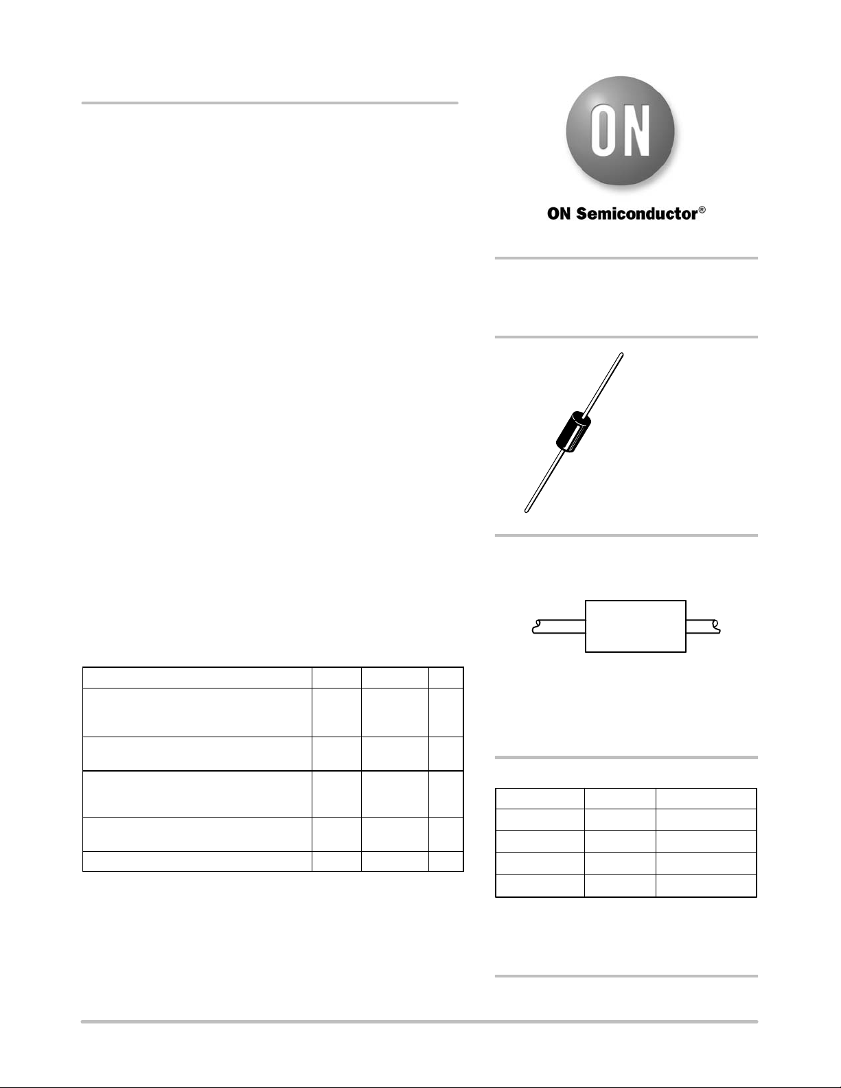
Axial Lead Rectifier
These devices employ the Schottky Barrier principle in a large area
metal−to−silicon power diode. State−of−the−art geometry features
epitaxial construction with oxide passivation and metal overlap
contact. Ideally suited for use as rectifiers in low−voltage,
high−frequency inverters, free wheeling diodes, and polarity
protection diodes.
Features
• High Current Capability
• Low Stored Charge, Majority Carrier Conduction
• Low Power Loss/High Efficiency
• Highly Stable Oxide Passivated Junction
• Guard−Ring for Stress Protection
• Low Forward Voltage
• High Surge Capacity
• These are Pb−Free Devices*
Mechanical Characteristics:
• Case: Epoxy, Molded
• Weight: 1.1 Gram (Approximately)
• Finish: All External Surfaces Corrosion Resistant and Terminal
Leads are Readily Solderable
• Lead and Mounting Surface Temperature for Soldering Purposes:
220°C Max. for 10 Seconds, 1/16″ from Case
• Polarity: Cathode indicated by Polarity Band
• ESD Protection: Human Body Model > 4000 V (Class 3)
Machine Model > 400 V (Class C)
MAXIMUM RATINGS
Rating Symbol Max Unit
Peak Repetitive Reverse Voltage
Working Peak Reverse Voltage
DC Blocking Voltage
V
RRM
V
RWM
V
R
45 V
Average Rectified Forward Current T
L
= 75°C
(Psi
JL
= 12°C/W, P.C. Board Mounting, Note 2)
I
O
8.0 A
Non−Repetitive Peak Surge Current
(Surge Applied at Rated Load Conditions
Halfwave, Single Phase, 60 Hz)
I
FSM
140 A
Operating and Storage Junction Tempera-
ture Range (Reverse Voltage Applied)
T
J
, T
stg
−65 to +125 °C
Voltage Rate of Change (Rated V
R
) dv/dt 10 V/ns
Stresses exceeding Maximum Ratings may damage the device. Maximum
Ratings are stress ratings only. Functional operation above the Recommended
Operating Conditions is not implied. Extended exposure to stresses above the
Recommended Operating Conditions may affect device reliability.
*For additional information on our Pb−Free strategy and soldering details, please
download the ON Semiconductor Soldering and Mounting Techniques
Reference Manual, SOLDERRM/D.
Device Package Shipping
†
ORDERING INFORMATION
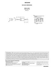
AXIAL LEAD
CASE 267−05
(DO−201AD)
STYLE 1
SCHOTTKY BARRIER
RECTIFIER
8.0 AMPERES
Preferred devices are recommended choices for future use
and best overall value.
80SQ045N Axial Lead* 500 Units/Box
80SQ045NRL Axial Lead*
MARKING DIAGRAM
80SQ
045N
YYWW G
G
YY = Year
WW = Work Week
G = Pb−Free Package
80SQ045NRLG Axial Lead* 1500/Tape & Ree
l
1500/Tape & Ree
l
80SQ045NG Axial Lead* 500 Units/Box
(Note: Microdot may be in either location)
†For information on tape and reel specifications,
including part orientation and tape sizes, please
refer to our Tape and Reel Packaging Specification
s
Brochure, BRD8011/D.
*This package is inherently Pb−Free.
http://onsemi.com
器件 Datasheet 文档搜索
AiEMA 数据库涵盖高达 72,405,303 个元件的数据手册,每天更新 5,000 多个 PDF 文件
