Datasheet 搜索 > 接口隔离器 > ADI(亚德诺) > ADUM4160BRIZ 数据手册 > ADUM4160BRIZ 数据手册 10/17 页

 器件3D模型
¥ 9.405
ADUM4160BRIZ 数据手册 - ADI(亚德诺)
制造商:
ADI(亚德诺)
分类:
接口隔离器
封装:
SOIC-16
描述:
ANALOG DEVICES ADUM4160BRIZ. 芯片, 数字隔离器, 70NS, SOIC-16
Pictures:
3D模型
符号图
焊盘图
引脚图
产品图
页面导航:
引脚图在P8Hot
典型应用电路图在P10
原理图在P1
封装尺寸在P14
型号编码规则在P14
封装信息在P4
功能描述在P1P8P10
技术参数、封装参数在P1P3P5P7
应用领域在P1P10P11
电气规格在P3

导航目录
ADUM4160BRIZ数据手册
Page:
of 17 Go
若手册格式错乱,请下载阅览PDF原文件
ADuM4160 Data Sheet
Rev. D | Page 10 of 16
APPLICATIONS INFORMATION
FUNCTIONAL DESCRIPTION
USB isolation in the D+/D− lines is challenging for several
reasons. First, access to the output enable signals is normally
required to control a transceiver. Some level of intelligence must
be built into the isolator to interpret the data stream and
determine when to enable and disable its upstream and down-
stream output buffers. Second, the signal must be faithfully
reconstructed on the output side of the coupler while retaining
precise timing and not passing transient states such as invalid
SE0 and SE1 states. In addition, the part must meet the low
power requirements of the suspend mode.
The iCoupler technology is based on edge detection, and,
therefore, lends itself well to the USB application. The flow of
data through the device is accomplished by monitoring the
inputs for activity and setting the direction for data transfer
based on a transition from the idle (J) state. When data
direction is established, data is transferred until either an end-
of-packet (EOP) or a sufficiently long idle state is encountered.
At this point, the coupler disables its output buffers and
monitors its inputs for the next activity
During the data transfers, the input side of the coupler holds its
output buffers disabled. The output side enables its output buffers
and disables edge detection from the input buffers. This allows
the data to flow in one direction without wrapping back through
the coupler making the iCoupler latch. Logic is included to
eliminate any artifacts due to different input thresholds of the
differential and single-ended buffers. The input state is transferred
across the isolation barrier as one of three valid states, J, K, or
SE0. The signal is reconstructed at the output side with a fixed
time delay from the input side differential input.
The iCoupler does not have a special suspend mode, nor does it
need one because its power supply current is below the suspend
current limit of 2.5 mA when the USB bus is idle.
The ADuM4160 is designed to interface with an upstream
facing low/full speed USB port by isolating the D+/D− lines.
An upstream facing port supports only one speed of operation,
thus, the speed related parameters, J/K logic levels, and D+/D−
slew rate are set to match the speed of the upstream facing
peripheral port (see
Table 1 0).
A control line on the downstream side of the ADuM4160 activates
a pull-up resistor integrated into the upstream side. This allows
the downstream port to control when the upstream port attaches
to the USB bus. The pin can be tied to the peripheral pull-up, a
control line, or the V
DD2
pin, depending on when the initial bus
connect is to be performed.
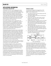
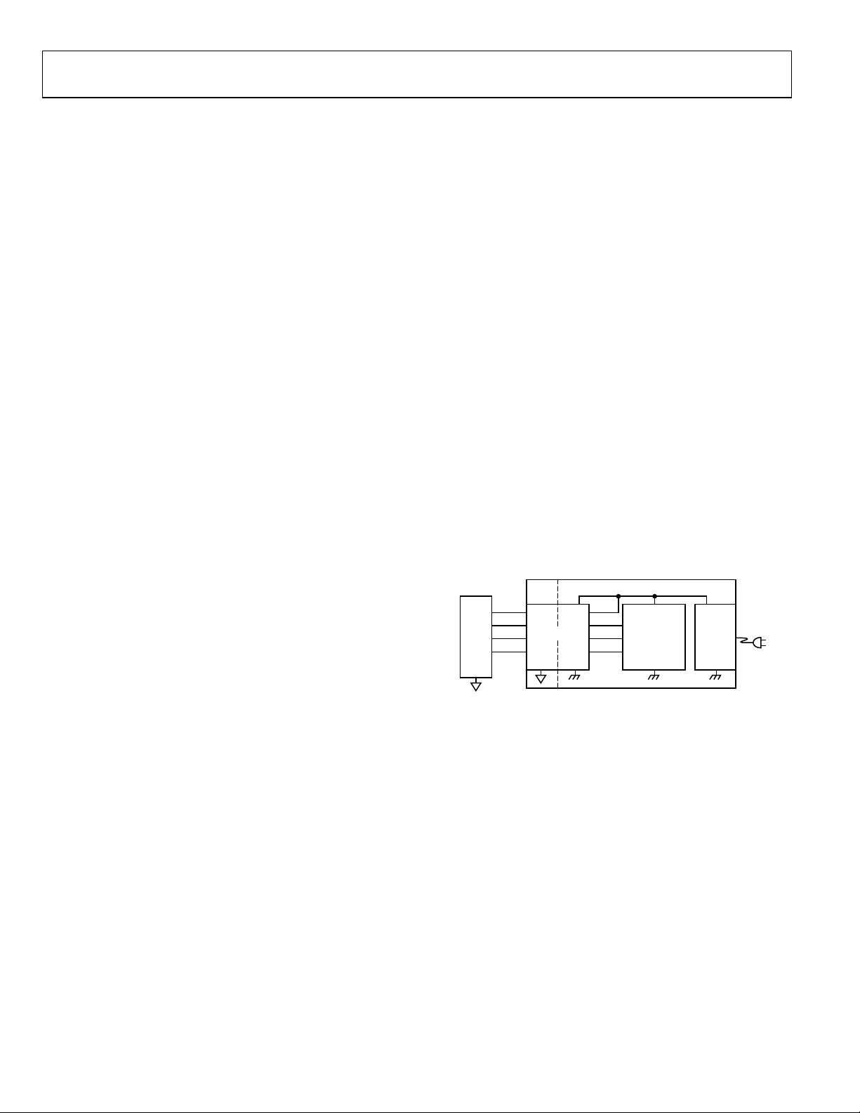
PRODUCT USAGE
The ADuM4160 is designed to be integrated into a USB
peripheral with an upstream facing USB port as shown in
Figure 4. The key design points are:
1. The USB host provides power for the upstream side of the
ADuM4160 through the cable.
2. The peripheral supply provides power to the downstream
side of the ADuM4160.
3. The DD+/DD− lines of the isolator interface with the
peripheral controller, and the UD+/UD− lines of the
isolator connect to the cable or host.
4. Peripheral devices have a fixed data rate that is set at design
time. The ADuM4160 has configuration pins, SPU and
SPD, that determine the buffer speed and logic convention
for each side. These must be set identically and match the
desired peripheral speed.
5. USB enumeration begins when either the UD+ or UD−
line is pulled high at the peripheral end of the USB cable,
which is the upstream side of the ADuM4160. Control of
the timing of this event is provided by the PIN input on the
downstream side of the coupler.
6. Pull-up and pull-down resistors are implemented inside
the coupler. Only external series resistors and bypass
capacitors are required for operation.
USB
HOST
ADuM4160
V
BUS1
V
BUS2
DD+
DD–
GND
1
DD+
3.3VV
DD2
DD–
PIN
MICRO-
CONTROLLER
POWER
SUPPLY
PERIPHERAL
08171-004
Figure 4. Typical Application
Other than the delayed application of pull-up resistors, the
ADuM4160 is transparent to USB traffic, and no modifications
to the peripheral design are required to provide isolation. The
isolator adds propagation delay to the signals comparable to a
hub and cable. Isolated peripherals must be treated as if there
were a built-in hub when determining the maximum number of
hubs in a data chain.
Hubs can be isolated like any other peripheral. Isolated hubs
can be created by placing an ADuM4160 on the upstream port
of a hub chip. This configuration can be made compliant if
counted as two hub delays. The hub chip allows the ADuM4160
to operate at full speed yet maintains compatibility with low
speed devices.
器件 Datasheet 文档搜索
AiEMA 数据库涵盖高达 72,405,303 个元件的数据手册,每天更新 5,000 多个 PDF 文件
