Datasheet 搜索 > 加速度传感器 > ADI(亚德诺) > ADXL202AE 数据手册 > ADXL202AE 数据手册 9/12 页
 器件3D模型
¥ 190.024
ADXL202AE 数据手册 - ADI(亚德诺)
制造商:
ADI(亚德诺)
分类:
加速度传感器
封装:
CLCC
描述:
低成本+ -2克双轴加速度计与占空比输出 Low-Cost +-2 g Dual-Axis Accelerometer with Duty Cycle Output
Pictures:
3D模型
符号图
焊盘图
引脚图
产品图
页面导航:
导航目录
ADXL202AE数据手册
Page:
of 12 Go
若手册格式错乱,请下载阅览PDF原文件
REV. A
ADXL202E
–9–
Setting the Bandwidth Using C
X
and C
Y
The ADXL202E has provisions for bandlimiting the X
FILT
and
Y
FILT
pins. Capacitors must be added at these pins to implement
low-pass filtering for antialiasing and noise reduction. The equa-
tion for the 3 dB bandwidth is:
F
–3 dB
=
1
2
π
(32 kΩ) × C(x, y)
()
or, more simply,
F
–3 dB
=
5 µF
C
(X ,Y )
The tolerance of the internal resistor (R
FILT
), can vary typically as
much as ±15% of its nominal value of 32 kΩ; so the bandwidth
will vary accordingly. A minimum capacitance of 1000 pF for
C
(X, Y)
is required in all cases.
Table I. Filter Capacitor Selection, C
X
and C
Y
Capacitor
Bandwidth Value
10 Hz 0.47 µF
50 Hz 0.10 µF
100 Hz 0.05 µF
200 Hz 0.027 µF
500 Hz 0.01 µF
5 kHz 0.001 µF
Setting the DCM Period with R
SET
The period of the DCM output is set for both channels by a single
resistor from R
SET
to ground. The equation for the period is:
T 2 =
R
SET
(Ω)
125 MΩ
A 125 kΩ resistor will set the duty cycle repetition rate to approxi-
mately 1 kHz, or 1 ms. The device is designed to operate at duty
cycle periods between 0.5 ms and 10 ms.
Table II. Resistor Values to Set T2
T2 R
SET
1 ms 125 kΩ
2 ms 250 kΩ
5 ms 625 kΩ
10 ms 1.25 MΩ
Note that the R
SET
should always be included, even if only an
analog output is desired. Use an R
SET
value between 500 kΩ
and 2 MΩ when taking the output from X
FILT
or Y
FILT
. The R
SET
resistor should be place close to the T2 Pin to minimize parasitic
capacitance at this node.
Selecting the Right Accelerometer
For most tilt sensing applications the ADXL202E is the most
appropriate accelerometer. Its higher sensitivity (12.5%/g) allows
the user to use a lower speed counter for PWM decoding while
maintaining high resolution. The ADXL210 should be used in
applications where accelerations of greater than ±2 g are expected.
DESIGN PROCEDURE FOR THE ADXL202E
The design procedure for using the ADXL202E with a duty cycle
output involves selecting a duty cycle period and a filter capacitor.
A proper design will take into account the application requirements
for bandwidth, signal resolution and acquisition time, as discussed
in the following sections.
Decoupling Capacitor C
DC
A 0.1 µF capacitor is recommended from V
DD
to COM for power
supply decoupling.
ST
The ST pin controls the self-test feature. When this pin is set to
V
DD
, an electrostatic force is exerted on the beam of the accelerom-
eter. The resulting movement of the beam allows the user to test if
the accelerometer is functional. The typical change in output will
be 10% at the duty cycle outputs (corresponding to 800 mg).
This pin may be left open circuit or connected to common in
normal use.
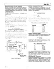
Duty Cycle Decoding
The ADXL202E’s digital output is a duty cycle modulator.
Acceleration is proportional to the ratio T1/T2. The nominal
output of the ADXL202E is:
0 g = 50% Duty Cycle
Scale factor is 12.5% Duty Cycle Change per g
These nominal values are affected by the initial tolerance of the
device including zero g offset error and sensitivity error.
T2 does not have to be measured for every measurement cycle.
It need only be updated to account for changes due to tempera-
ture, (a relatively slow process). Since the T2 time period is shared
by both X and Y channels, it is necessary only to measure it on
one channel of the ADXL202E. Decoding algorithms for various
microcontrollers have been developed. Consult the appropriate
Application Note.
ANALOG
TO
DUTY
CYCLE
(ADC)
C
O
U
N
T
E
R
P
X
OUT
Y
OUT
DEMOD
DEMOD
R
FILT
32k
R
FILT
32k
ADXL202E
R
SET
T2
C
Y
Y
FILT
SELF-TEST
X
FILT
C
X
OSCILLATOR
COM
Y SENSOR
X SENSOR
3V TO 5.25V
V
DD
C
DC
T1
T2
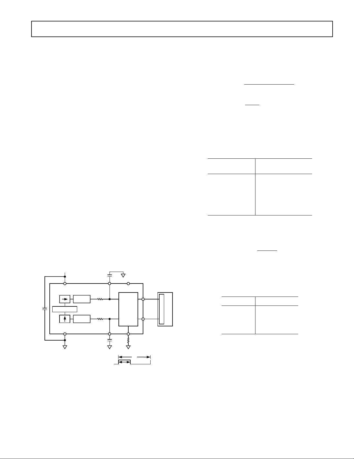
A(g) = (T1/T2 – 0.5)/12.5%
0g = 50% DUTY CYCLE
T2 = R
SET
/125M
Figure 3. Block Diagram
器件 Datasheet 文档搜索
AiEMA 数据库涵盖高达 72,405,303 个元件的数据手册,每天更新 5,000 多个 PDF 文件
