Datasheet 搜索 > 微控制器 > Microchip(微芯) > AT32UC3L032-D3HT 数据手册 > AT32UC3L032-D3HT 数据手册 105/849 页

¥ 28.547
AT32UC3L032-D3HT 数据手册 - Microchip(微芯)
制造商:
Microchip(微芯)
分类:
微控制器
封装:
UFLGA-48
描述:
32位微控制器 - MCU UC3L-32KB Flash 85C
Pictures:
3D模型
符号图
焊盘图
引脚图
产品图
页面导航:
引脚图在P186P294P361P416P457P491P520P596P597P623P624P690Hot
典型应用电路图在P493
原理图在P5P42P105P140P141P152P159P189P193P195P251P280
封装尺寸在P803P804P805
型号编码规则在P807P838P839
封装信息在P803P804P805
功能描述在P11P43P78P106P126P141P153P187P252P281P294P316
应用领域在P1
电气规格在P10P80P100P160P187P190P192P194P197P198P222P251
导航目录
AT32UC3L032-D3HT数据手册
Page:
of 849 Go
若手册格式错乱,请下载阅览PDF原文件
105
32099I–01/2012
AT32UC3L016/32/64
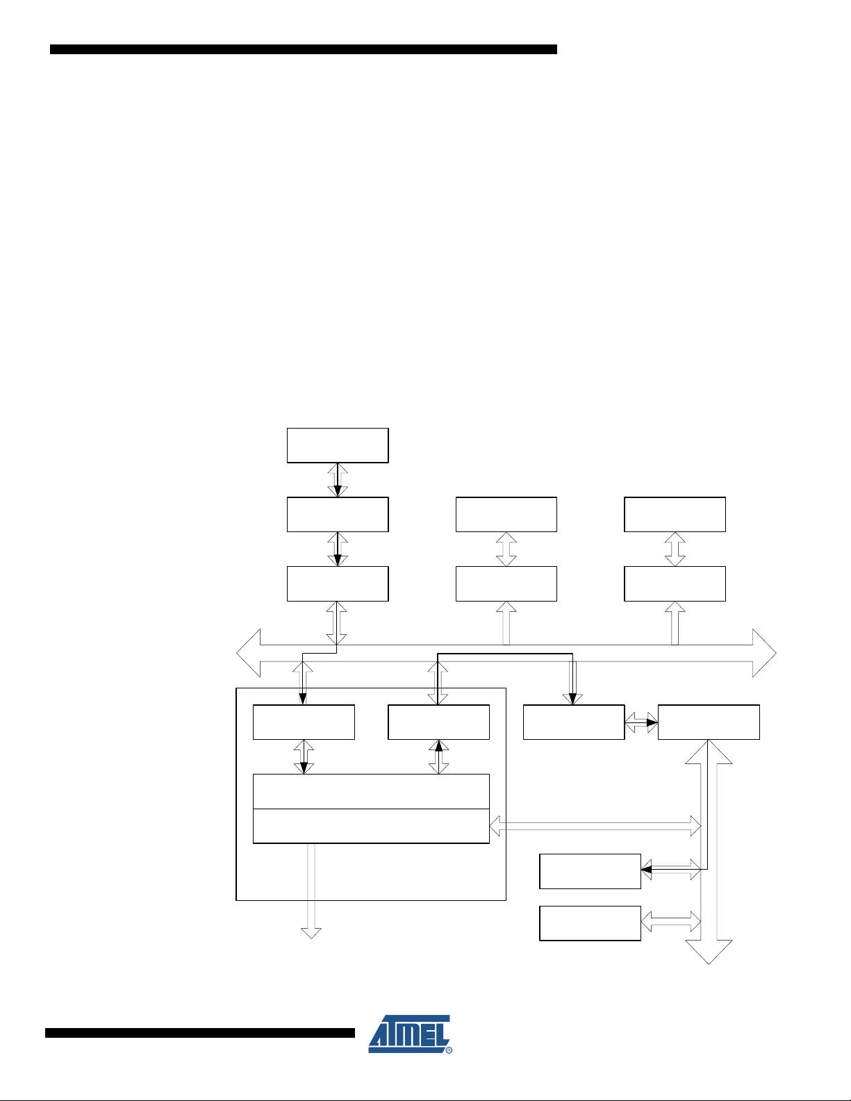
9.3 Block Diagram
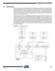
Figure 9-1 presents the SAU integrated in an example system with a CPU, some memories,
some peripherals, and a bus system. The SAU is connected to both the Peripheral Bus (PB) and
the High Speed Bus (HSB). Configuration of the SAU is done via the PB, while memory
accesses are done via the HSB. The SAU receives an access on its HSB slave interface,
remaps it, checks that the channel is unlocked, and if so, initiates a transfer on its HSB master
interface to the remapped address.
The thin arrows in Figure 9-1 exemplifies control flow when using the SAU. The CPU wants to
read the RX Buffer in the USART. The MPU has been configured to protect all registers in the
USART from user mode access, while the SAU has been configured to remap the RX Buffer into
a memory space that is not protected by the MPU. This unprotected memory space is mapped
into the SAU HSB slave space. When the CPU reads the appropriate address in the SAU, the
SAU will perform an access to the desired RX buffer register in the USART, and thereafter return
the read results to the CPU. The return data flow will follow the opposite direction of the control
flow arrows in Figure 9-1.
Figure 9-1. SAU Block Diagram
SAU Channel
Bus master
MPU
CPU
Bus slave
USART
PWM
Bus slave Bus master
Bus slave
Flash
Bus slave
RAM
Bus bridge
SAU Configuration
Interrupt
request
High Speed Bus
SAU
Peripheral Bus
器件 Datasheet 文档搜索
AiEMA 数据库涵盖高达 72,405,303 个元件的数据手册,每天更新 5,000 多个 PDF 文件
