Datasheet 搜索 > 8位微控制器 > ATMEL(爱特美尔) > ATMEGA324P-20MU 数据手册 > ATMEGA324P-20MU 数据手册 117/439 页
 器件3D模型
¥ 30.96
ATMEGA324P-20MU 数据手册 - ATMEL(爱特美尔)
制造商:
ATMEL(爱特美尔)
分类:
8位微控制器
封装:
VQFN-44
描述:
ATMEL ATMEGA324P-20MU 微控制器, 8位, 低功率高性能, ATmega, 20 MHz, 32 KB, 2 KB, 44 引脚, VQFN
Pictures:
3D模型
符号图
焊盘图
引脚图
产品图
页面导航:
引脚图在P2P6P74P93P111P139Hot
原理图在P4P9P72P93P94P96P97P112P117P118P120P122
封装尺寸在P423P424P425
型号编码规则在P420P421P422P428
封装信息在P423P428
应用领域在P41P50P62P65P276P280P293P294
导航目录
ATMEGA324P-20MU数据手册
Page:
of 439 Go
若手册格式错乱,请下载阅览PDF原文件
117
8011N–AVR–01/10
ATmega164P/324P/644P
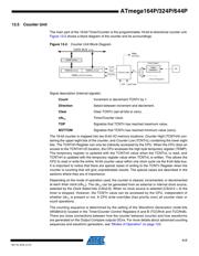
13.5 Counter Unit
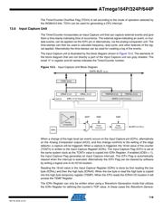
The main part of the 16-bit Timer/Counter is the programmable 16-bit bi-directional counter unit.
Figure 13-2 shows a block diagram of the counter and its surroundings.
Figure 13-2. Counter Unit Block Diagram
Signal description (internal signals):
Count Increment or decrement TCNTn by 1.
Direction Select between increment and decrement.
Clear Clear TCNTn (set all bits to zero).
clk
T
n
Timer/Counter clock.
TOP Signalize that TCNTn has reached maximum value.
BOTTOM Signalize that TCNTn has reached minimum value (zero).
The 16-bit counter is mapped into two 8-bit I/O memory locations: Counter High (TCNTnH) con-
taining the upper eight bits of the counter, and Counter Low (TCNTnL) containing the lower eight
bits. The TCNTnH Register can only be indirectly accessed by the CPU. When the CPU does an
access to the TCNTnH I/O location, the CPU accesses the high byte temporary register (TEMP).
The temporary register is updated with the TCNTnH value when the TCNTnL is read, and
TCNTnH is updated with the temporary register value when TCNTnL is written. This allows the
CPU to read or write the entire 16-bit counter value within one clock cycle via the 8-bit data bus.
It is important to notice that there are special cases of writing to the TCNTn Register when the
counter is counting that will give unpredictable results. The special cases are described in the
sections where they are of importance.
Depending on the mode of operation used, the counter is cleared, incremented, or decremented
at each timer clock (clk
T
n
). The clk
T
n
can be generated from an external or internal clock source,
selected by the Clock Select bits (CSn2:0). When no clock source is selected (CSn2:0 = 0) the
timer is stopped. However, the TCNTn value can be accessed by the CPU, independent of
whether clk
T
n
is present or not. A CPU write overrides (has priority over) all counter clear or
count operations.
The counting sequence is determined by the setting of the Waveform Generation mode bits
(WGMn3:0) located in the Timer/Counter Control Registers A and B (TCCRnA and TCCRnB).
There are close connections between how the counter behaves (counts) and how waveforms
are generated on the Output Compare outputs OCnx. For more details about advanced counting
sequences and waveform generation, see ”Modes of Operation” on page 123.
TEMP (8-bit)
DATA BUS (8-bit)
TCNTn (16-bit Counter)
TCNTnH (8-bit) TCNTnL (8-bit)
Control Logic
Count
Clear
Direction
TOVn
(Int.Req.)
Clock Select
TOP BOTTOM
Tn
Edge
Detector
( From Prescaler )
clk
Tn
器件 Datasheet 文档搜索
AiEMA 数据库涵盖高达 72,405,303 个元件的数据手册,每天更新 5,000 多个 PDF 文件
