Datasheet 搜索 > 开发套件 > TI(德州仪器) > BQ24195EVM-193 数据手册 > BQ24195EVM-193 数据手册 2/52 页

¥ 866.991
BQ24195EVM-193 数据手册 - TI(德州仪器)
制造商:
TI(德州仪器)
分类:
开发套件
描述:
TEXAS INSTRUMENTS BQ24195EVM-193 评估模块, BQ24195EVM-193
Pictures:
3D模型
符号图
焊盘图
引脚图
产品图
页面导航:
引脚图在P4P5Hot
典型应用电路图在P36P37P38
原理图在P12
封装尺寸在P45P47P48
标记信息在P45
封装信息在P44P45P46P47P48
技术参数、封装参数在P5
应用领域在P1P52
电气规格在P6P7P8P9
导航目录
BQ24195EVM-193数据手册
Page:
of 52 Go
若手册格式错乱,请下载阅览PDF原文件

bq24190
,
bq24192
,
bq24192I
SLUSAW5B –JANUARY 2012–REVISED DECEMBER 2014
www.ti.com
Table of Contents
9.3 Feature Description................................................. 13
1 Features.................................................................. 1
9.4 Device Functional Modes........................................ 27
2 Applications ........................................................... 1
9.5 Register Map........................................................... 28
3 Description............................................................. 1
10 Application and Implementation........................ 36
4 Revision History..................................................... 2
10.1 Application Information.......................................... 36
5 Description (Continued)........................................ 3
10.2 Typical Application................................................ 36
6 Device Comparison Table..................................... 3
11 Power Supply Recommendations ..................... 41
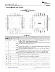
7 Pin Configuration and Functions......................... 4
12 Layout................................................................... 41
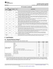
8 Specifications......................................................... 5
12.1 Layout Guidelines ................................................. 41
8.1 Absolute Maximum Ratings ...................................... 5
12.2 Layout Example .................................................... 42
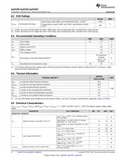
8.2 ESD Ratings ............................................................ 6
13 Device and Documentation Support................. 43
8.3 Recommended Operating Conditions....................... 6
13.1 Documentation Support ....................................... 43
8.4 Thermal Information.................................................. 6
13.2 Related Links ........................................................ 43
8.5 Electrical Characteristics........................................... 6
13.3 Trademarks........................................................... 43
8.6 Typical Characteristics.............................................. 9
13.4 Electrostatic Discharge Caution............................ 43
9 Detailed Description............................................ 12
13.5 Glossary................................................................ 43
9.1 Overview ................................................................. 12
14 Mechanical, Packaging, and Orderable
9.2 Functional Block Diagram....................................... 12
Information........................................................... 44
4 Revision History
Changes from Revision A (October 2012) to Revision B Page
• Aligned package description throughout datasheet................................................................................................................ 1
• Added ESD Ratings, Feature Description, Device Functional Modes, Application and Implementation, Power Supply
Recommendations, Layout, Device and Documentation Support, Mechanical, Packaging, Orderable Information. ........... 1
• Added Feature: Compatible with MaxLife Technology for Faster Charging When Used in Conjunction With bq27531 ....... 1
• Changed V
SLEEPZ
, V
BAT_DPL_HY
, V
BATGD
, I
CHG_20pct
, V
SHORT
, I
ADPT_DPM
, K
ILIM
, V
BTST_REFRESH
in Electrical Characteristics.......... 6
• Added –40°C to 85° to I
BAT
Test Condition............................................................................................................................. 6
• Added REG00[6:3] = 0110 (4.36 V) or 1011 (4.76 V) to V
INDPM_REG_ACC
Test Conditions...................................................... 8
• Added Typical input current of 1.5 A based on KLIM to I
ADPT_DPM
Test Conditions ............................................................... 8
• Added a MIN value of 435 to K
ILIM
.......................................................................................................................................... 8
• Deleted T
Junction_REG
MIN and MAX......................................................................................................................................... 8
• Added rising to V
HTF
parameter ............................................................................................................................................. 8
• Deleted V
REGN
, V
VBUS
= 5 V, I
REGN
= 20 mA MAX value......................................................................................................... 9
• Changed Functional Block Diagram..................................................................................................................................... 12
• Changed Charging Current in Table 4 ................................................................................................................................. 18
• Changed REG09[5:4] to REG08[5:4] in Charging Termination section ............................................................................... 21
• Added or when FORCE_20PCT (REG02[0]) bit is set, to Charging Safety Timer description............................................ 22
• Added last paragraph to Charging Safety Timer description................................................................................................ 22
• Added twice to Host Mode and Default Mode description ................................................................................................... 27
• Changed REG05[5:4]=11 to REG05[5:4]=00 in Host Mode and Default Mode description................................................. 27
• Changed Charge Current Control Register REG02 Bit 0 description .................................................................................. 31
• Changed Charge Current Control Register REG02 Bit 0 note............................................................................................. 31
• Changed REG05 Bit 0 from JEITA ISET (0°C-10°C) to Reserved ...................................................................................... 32
• Changed REG07 Bit 4 from JEITA_VSET (45°C to 60°C) to Reserved.............................................................................. 33
• Changed BOOT to BTST in Figure 38 ................................................................................................................................. 37
• Changed BOOT to BTST in Figure 39 ................................................................................................................................. 37
• Changed bq24193 to bq24192 in Figure 42......................................................................................................................... 39
2 Submit Documentation Feedback Copyright © 2012–2014, Texas Instruments Incorporated
Product Folder Links: bq24190 bq24192 bq24192I
器件 Datasheet 文档搜索
AiEMA 数据库涵盖高达 72,405,303 个元件的数据手册,每天更新 5,000 多个 PDF 文件
