Datasheet 搜索 > 陶瓷电容 > KEMET Corporation(基美) > C0805C820J5GALTU 数据手册 > C0805C820J5GALTU 数据手册 4/7 页

¥ 0.116
C0805C820J5GALTU 数据手册 - KEMET Corporation(基美)
制造商:
KEMET Corporation(基美)
分类:
陶瓷电容
封装:
0805
Pictures:
3D模型
符号图
焊盘图
引脚图
产品图
C0805C820J5GALTU数据手册
Page:
of 7 Go
若手册格式错乱,请下载阅览PDF原文件
©KEMET Electronics Corporation, P.O. Box 5928, Greenville, S.C. 29606, (864) 963-6300
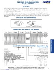
Performance Notes
1. Cover Tape Break Force: 1.0 Kg Minimum.
2. Cover Tape Peel Strength: The total peel strength of the cover tape from the carrier tape shall be:
Tape Width Peel Strength
8 mm 0.1 Newton to 1.0 Newton (10g to 100g)
12 mm 0.1 Newton to 1.3 Newton (10g to 130g)
The direction of the pull shall be opposite the direction of the carrier tape travel. The pull angle of the carrier
tape shall be 165 to 180 from the plane of the carrier tape. During peeling, the carrier and/or cover tape
shall be pulled at a velocity of 300 ±10 mm/minute.
3. Reel Sizes: Molded tantalum capacitors are available on either 180 mm (7") reels (standard) or 330 mm (13")
reels (with C-7280). Note that 13” reels are preferred.
4. Labeling: Bar code labeling (standard or custom) shall be on the side of the reel opposite the sprocket holes.
Refer to EIA-556.
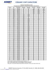
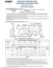
Embossed Carrier Tape Configuration: Figure 1
NOTES
1. B1 dimension is a reference dimension for tape feeder clearance only.
2. The embossment hole location shall be measured from the sprocket hole controlling the location of the embossment. Dimensions of
embossment location and hole location shall be applied independent of each other.
3. Tape with components shall pass around radius “R” without damage (see sketch A). The minimum trailer length (Fig. 2) may require
additional length to provide R min. for 12 mm embossed tape for reels with hub diameters approaching N min. (Table 2)
4. The cavity defined by A
0
, B
0
, and K
0
shall be configured to surround the part with sufficient clearance such that the chip does not pro-
trude beyond the sealing plane of the cover tape, the chip can be removed from the cavity in a vertical direction without mechanical
restriction, rotation of the chip is limited to 20 degrees maximum in all 3 planes, and lateral movement of the chip is restricted to 0.5 mm
maximum in the pocket (not applicable to vertical clearance.)
Table 1 — EMBOSSED TAPE DIMENSIONS (Metric will govern)
Constant Dimensions — Millimeters (Inches)
Tape Size D
0
EP
0
P
2
T Max T
1
Max
8 mm 1.5 1.75 ±0.10 4.0 ±0.10 2.0 ±0.05 0.600 0.100
and +0.10 -0.0
12 mm (0.059 (0.069 ±0.004) (0.157 ±0.004) (0.079 ±0.002) (0.024) (0.004)
+0.004, -0.0)
Variable Dimensions — Millimeters (Inches)
Tape Size Pitch B
1
Max. D
1
Min. F P
1
R Min. T
2
Max W A
0
B
0
K
0
Note 1 Note 2 Note 3 Note 4
8 mm Single 4.4 1.0 3.5 ±0.05 4.0 ±0.10 25.0 2.5 8.0 ±0.30
(4 mm)
(0.173) (0.039) (0.138 ±0.002) (0.157 ±0.004) (0.984) (0.098) (.315 ±0.012)
12 mm Double 8.2 1.5 5.5 ±0.05 8.0 ±0.10 30.0 4.6 12.0 ±0.30
(8 mm) (0.323) (0.059) (0.217 ±0.002) (0.315 ±0.004) (1.181) (0.181) (0.472 ±0.012)
TANTALUM, CERAMIC AND
ALUMINUM CHIP CAPACITORS
Packaging Information
94
Downloaded from Elcodis.com electronic components distributor
器件 Datasheet 文档搜索
AiEMA 数据库涵盖高达 72,405,303 个元件的数据手册,每天更新 5,000 多个 PDF 文件
