Datasheet 搜索 > 接口芯片 > Maxim Integrated(美信) > DS2480B+ 数据手册 > DS2480B+ 数据手册 6/32 页
 器件3D模型
¥ 31.162
DS2480B+ 数据手册 - Maxim Integrated(美信)
制造商:
Maxim Integrated(美信)
分类:
接口芯片
封装:
SOIC-8
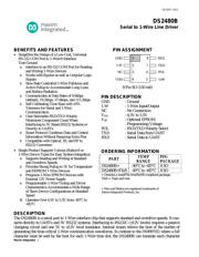
描述:
MAXIM INTEGRATED PRODUCTS DS2480B+ 芯片, 串行线路驱动器, 2480, SOIC8
Pictures:
3D模型
符号图
焊盘图
引脚图
产品图
页面导航:
引脚图在P1Hot
型号编码规则在P1
封装信息在P1


导航目录
DS2480B+数据手册
Page:
of 32 Go
若手册格式错乱,请下载阅览PDF原文件

DS2480B
In addition to the command codes explained in the subsequent sections the DS2480B understands the
following reserved command codes:
E1h switch to Data Mode
E3h switch to Command Mode
F1h pulse termination
Except for these reserved commands, the Search Accelerator control and the first byte after power-on
reset or master reset cycle, every legal command byte generates a response byte. The pulse termination
code triggers the response byte of the terminated pulse command. Illegal command bytes do not generate
a command response byte.
COMMUNICATION COMMANDS
The DS2480B supports four communication function commands: Reset, Single Bit, Pulse, and Search
Accelerator control. Details on the assignment of each bit of the command codes are shown in Table 1.
The corresponding command response bytes are detailed in Table 2. The Reset, Search Accelerator
Control and Single Bit commands include bits to select the 1-Wire communication speed (standard,
flexible, Overdrive). Even if a command does not generate activity on the 1-Wire bus, these bits are
latched inside the device and will take effect immediately.
Reset
The Reset command must be used to begin all 1-Wire communication. The speed selection included in
the command code immediately takes effect. The response byte includes a code for the reaction on the
1-Wire bus (bits 0 and 1) and a code for the chip revision (bits 2 to 4).
Single Bit
The Single Bit command is used to generate a single time slot on the 1-Wire bus at the speed indicated by
bits 2 and 3. The type of the time slot (Write-0 or Write-1) is determined by the logic value of bit 4. A
Read Data time slot is identical to the Write-1 time slot. Bits 0 and 1 of the response byte transmitted by
the DS2480B at the end of the time slot reveal the value found on the 1-Wire bus when reading.
For a time slot without a subsequent strong pullup, bit 1 of the command must be set to 0. For a time slot
immediately followed by a strong pullup bit 1 must be set to 1. As soon as the strong pullup is over, the
device will send a second response byte, code EFh (read 1) or ECh (read 0), depending on the value
found on the 1-Wire bus when reading.
Maxim Integrated ............................................................................................................................................................................................. 6
器件 Datasheet 文档搜索
AiEMA 数据库涵盖高达 72,405,303 个元件的数据手册,每天更新 5,000 多个 PDF 文件
