Datasheet 搜索 > TI(德州仪器) > DS90UB947TRGCRQ1 数据手册 > DS90UB947TRGCRQ1 数据手册 6/81 页
 器件3D模型
¥ 28.321
DS90UB947TRGCRQ1 数据手册 - TI(德州仪器)
制造商:
TI(德州仪器)
封装:
VQFN-64
描述:
1080p 双路 FPD-Link III 串行器 64-VQFN -40 to 105
Pictures:
3D模型
符号图
焊盘图
引脚图
产品图
页面导航:
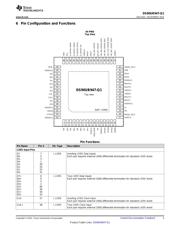
引脚图在P3P4P5P70P71Hot
典型应用电路图在P65P66P67P68
原理图在P14
封装尺寸在P74P76P77
标记信息在P74
封装信息在P73P74P75P76P77
功能描述在P37P38P39P40P41P42P43P44P45P46P47P48
技术参数、封装参数在P6P73
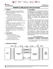
应用领域在P1P65P66P67P68P81
电气规格在P7P8
导航目录
DS90UB947TRGCRQ1数据手册
Page:
of 81 Go
若手册格式错乱,请下载阅览PDF原文件
DS90UB947-Q1
SNLS454 –NOVEMBER 2014
www.ti.com
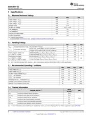
7 Specifications
7.1 Absolute Maximum Ratings
MIN MAX UNIT
Supply Voltage – V
DD11
−0.3 1.7 V
Supply Voltage – V
DD18
-0.3 2.5 V
Supply Voltage – V
DDIO
−0.3 2.5 V
OpenLDI Inputs -0.3 2.75 V
LVCMOS I/O Voltage −0.3 (V
DDIO
+ 0.3) V
1.8V Tolerant I/O -0.3 2.5 V
3.3V Tolerant I/O -0.3 4.0 V
FPD-Link III Output Voltage −0.3 1.7 V
Junction Temperature 150 °C
For soldering specifications:
see product folder at www.ti.com and www.ti.com/lit/an/snoa549c/snoa549c.pdf
7.2 Handling Ratings
MIN MAX UNIT
T
stg
Storage temperature range 64 Lead VQFN Package -65 +150 °C
Human body model (HBM), per AEC Q100-002
(1)
-2 +2 kV
V
(ESD)
Electrostatic discharge
Charged device model (CDM), per AEC Q100-011 -750 +750 V
Air Discharge (D
OUT0+
, D
OUT0-
, D
OUT1+
, D
OUT1-
) -15 +15
ESD Rating (IEC 61000-4-2)
kV
R
D
= 330Ω, C
S
= 150pF
Contact Discharge (D
OUT0+
, D
OUT0-
, D
OUT1+
, D
OUT1-
) -8 +8
ESD Rating (ISO10605) Air Discharge (D
OUT0+
, D
OUT0-
, D
OUT1+
, D
OUT1-
) -15 +15
R
D
= 330Ω, C
S
= 150pF kV
Contact Discharge (D
OUT0+
, D
OUT0-
, D
OUT1+
, D
OUT1-
) -8 +8
R
D
= 2KΩ, C
S
= 150pF or 330pF
(1) AEC Q100-002 indicates HBM stressing is done in accordance with the ANSI/ESDA/JEDEC JS-001 specification.
7.3 Recommended Operating Conditions
MIN NOM MAX UNIT
Supply Voltage (V
DD11
) 1.045 1.1 1.155 V
Supply Voltage (V
DD18
) 1.71 1.8 1.89 V
LVCMOS Supply Voltage (V
DDIO
) 1.71 1.8 1.89 V
V
DDI2C
, 1.8V Operation 1.71 1.8 1.89 V
V
DDI2C
, 3.3V Operation 3.135 3.3 3.465 V
Operating Free Air Temperature (T
A
) −40 +25 +105 °C
OpenLDI Clock Frequency (Single Link) 25 170 MHz
OpenLDI Clock Frequency (Dual Link) 50 170 MHz
7.4 Thermal Information
VQFN
THERMAL METRIC
(1)
UNIT
64 PINS
R
θJA
Junction-to-ambient thermal resistance 25.8
R
θJC(top)
Junction-to-case (top) thermal resistance 11.4
R
θJB
Junction-to-board thermal resistance 5.1
°C/W
ψ
JT
Junction-to-top characterization parameter 0.2
ψ
JB
Junction-to-board characterization parameter 5.1
R
θJC(bot)
Junction-to-case (bottom) thermal resistance 0.8
(1) For more information about traditional and new thermal metrics, see the IC Package Thermal Metrics application report, SPRA953.
6 Submit Documentation Feedback Copyright © 2014, Texas Instruments Incorporated
Product Folder Links: DS90UB947-Q1
器件 Datasheet 文档搜索
AiEMA 数据库涵盖高达 72,405,303 个元件的数据手册,每天更新 5,000 多个 PDF 文件
