Datasheet 搜索 > Omron(欧姆龙) > EESX672PWR1M 数据手册 > EESX672PWR1M 数据手册 4/10 页


¥ 165.097
EESX672PWR1M 数据手册 - Omron(欧姆龙)
制造商:
Omron(欧姆龙)
Pictures:
3D模型
符号图
焊盘图
引脚图
产品图
页面导航:
导航目录
EESX672PWR1M数据手册
Page:
of 10 Go
若手册格式错乱,请下载阅览PDF原文件
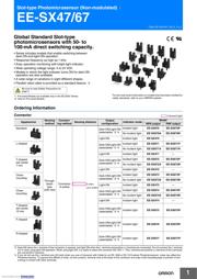
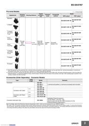
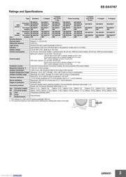
EE-SX47/67
4
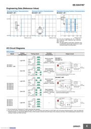
Engineering Data (Reference Value)
I/O Circuit Diagrams
NPN Output
*1. Do not connect the L terminal to 0 V when using dark-ON operation.
*2. If you do not use the L terminal wire ((2) pink) when you use a Connector with Cable for an EE-1006 or EE-1010-series Photomicrosensor, noise may affect the
Photomicrosensor. To prevent the effects of noise, cut the unused L terminal wire at the base of the connector and wrap it with insulating tape to prevent it from
coming in contact with other terminals.
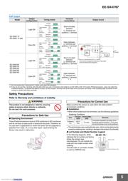
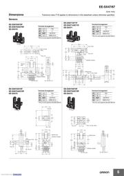
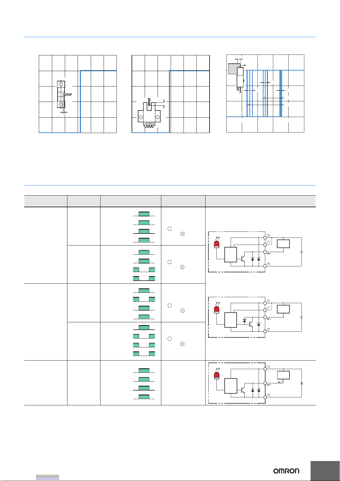
Sensing Position Characteristics Sensing Position Characteristics Repeated Sensing Position Characteristics
EE-SX47@/67@ EE-SX47@/67@ EE-SX47@/67@
Model
Output
configuration
Timing charts
Terminal
connections
Output circuit
EE-SX67@
EE-SX67@-WR
Light-ON
Short-circuited
between
terminal and
positive terminal
EE-SX67@
EE-SX67@A
EE-SX67@-WR
Dark-ON
Open between
terminal and
positive terminal
*1 *2
EE-SX670A
EE-SX671A
EE-SX672A
EE-SX673A
EE-SX674A
Light-ON
Short-circuited
between
terminal and
positive terminal
Dark-ON
Open between
terminal and
positive terminal
*1 *2
EE-SX470
EE-SX471
EE-SX472
EE-SX473
EE-SX474
Light-ON ---
Dark-ON
Light-ON
0 1.0 2.0 3.0 4.0 5.0 6.0
Distance d (mm)
d
0 1.0 2.0 3.0 4.0 5.0 6.0
Distance d (mm)
Dark-ON
Light-ON
d
d
0 3.20 3.22 3.24 3.26 3.28
Distance d (mm)
Ta = −25°C
Ta = 55°C
Ta = 25°C
Δd3 Δd1
Δd2
Δd4
Δd5
Dark-ON
Light-ON
Vcc =12 V, No. of repetitions: 20, Δd1 = 0.002 mm,
Δd2 = 0.004 mm, Δd3 = 0.005 mm, Δd4 = 0.02 mm,
Δd5 = 0.04 mm
Note: The data applies to dark status. Operation may
be affected by external light interference or light
coming through the sensing object.
Incident
Interrupted
ON
OFF
ON
OFF
Operates
Releases
Light indicator
(red)
Output
transistor
Load
(e.g., relay)
L
5 to
24 VDC
(Control output)
100 mA max.
Load
Main
circuit
L
OUT
IC
Light indicator
(red)
*The terminal arrangement depends on the model.
Check the dimensional diagrams.
*
5 to
24 VDC
(Control output)
100 mA max.
Load
Main
circuit
L
OUT
IC
Light indicator
(red)
*The terminal arrangement depends on the model.
Check the dimensional diagrams.
*
Incident
Interrupted
ON
OFF
ON
OFF
Operates
Releases
Light indicator
(red)
Output
transistor
Load
(e.g., relay)
L
Incident
Interrupted
ON
OFF
ON
OFF
Operates
Releases
Light indicator
(red)
Output
transistor
Load
(e.g., relay)
L
Incident
Interrupted
ON
OFF
ON
OFF
Operates
Releases
Light indicator
(red)
Output
transistor
Load
(e.g., relay)
L
Incident
Interrupted
ON
OFF
ON
OFF
Operates
Releases
Light indicator
(red)
Output
transistor
Load
(relay)
5 to
24 VDC
IC
OUT
Light indicator
(red)
Load
Main
circuit
Downloaded from Arrow.com.Downloaded from Arrow.com.Downloaded from Arrow.com.Downloaded from Arrow.com.
器件 Datasheet 文档搜索
AiEMA 数据库涵盖高达 72,405,303 个元件的数据手册,每天更新 5,000 多个 PDF 文件
