Datasheet 搜索 > FPGA芯片 > Altera(阿尔特拉) > EP1C12F324C7N 数据手册 > EP1C12F324C7N 数据手册 27/385 页

 器件3D模型
¥ 627.157
EP1C12F324C7N 数据手册 - Altera(阿尔特拉)
制造商:
Altera(阿尔特拉)
分类:
FPGA芯片
封装:
FBGA-324
Pictures:
3D模型
符号图
焊盘图
引脚图
产品图
页面导航:
引脚图在P162P314P317P377Hot
典型应用电路图在P25P27P29P31P255P273
原理图在P22P141P341
封装尺寸在P12P117P377P383P384
型号编码规则在P11P117
功能描述在P21P148P149P150P152P336P338P340
技术参数、封装参数在P85P86P87P88P89P90P94P113P114P142P224P225
应用领域在P102P203P228
电气规格在P225
导航目录
EP1C12F324C7N数据手册
Page:
of 385 Go
若手册格式错乱,请下载阅览PDF原文件

Altera Corporation 2–7
May 2008 Preliminary
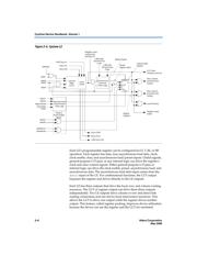
Logic Elements
functions. Another special packing mode allows the register output to
feed back into the LUT of the same LE so that the register is packed with
its own fan-out LUT. This provides another mechanism for improved
fitting. The LE can also drive out registered and unregistered versions of
the LUT output.
LUT Chain and Register Chain
In addition to the three general routing outputs, the LEs within a LAB
have LUT chain and register chain outputs. LUT chain connections allow
LUTs within the same LAB to cascade together for wide input functions.
Register chain outputs allow registers within the same LAB to cascade
together. The register chain output allows a LAB to use LUTs for a single
combinatorial function and the registers to be used for an unrelated shift
register implementation. These resources speed up connections between
LABs while saving local interconnect resources. “MultiTrack
Interconnect” on page 2–12 for more information on LUT chain and
register chain connections.
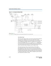
addnsub Signal
The LE's dynamic adder/subtractor feature saves logic resources by
using one set of LEs to implement both an adder and a subtractor. This
feature is controlled by the LAB-wide control signal addnsub. The
addnsub signal sets the LAB to perform either A + B or A − B. The LUT
computes addition; subtraction is computed by adding the two's
complement of the intended subtractor. The LAB-wide signal converts to
two's complement by inverting the B bits within the LAB and setting
carry-in = 1 to add one to the least significant bit (LSB). The LSB of an
adder/subtractor must be placed in the first LE of the LAB, where the
LAB-wide addnsub signal automatically sets the carry-in to 1. The
Quartus II Compiler automatically places and uses the adder/subtractor
feature when using adder/subtractor parameterized functions.
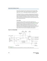
LE Operating Modes
The Cyclone LE can operate in one of the following modes:
■ Normal mode
■ Dynamic arithmetic mode
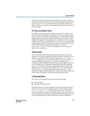
Each mode uses LE resources differently. In each mode, eight available
inputs to the LE⎯the four data inputs from the LAB local interconnect,
carry-in0 and carry-in1 from the previous LE, the LAB carry-in
from the previous carry-chain LAB, and the register chain connection⎯are
directed to different destinations to implement the desired logic function.
LAB-wide signals provide clock, asynchronous clear, asynchronous
器件 Datasheet 文档搜索
AiEMA 数据库涵盖高达 72,405,303 个元件的数据手册,每天更新 5,000 多个 PDF 文件
