Datasheet 搜索 > CPLD芯片 > Altera(阿尔特拉) > EPM1270T144C5N 数据手册 > EPM1270T144C5N 数据手册 4/10 页
 器件3D模型
¥ 438.443
EPM1270T144C5N 数据手册 - Altera(阿尔特拉)
制造商:
Altera(阿尔特拉)
分类:
CPLD芯片
封装:
TQFP-144
描述:
ALTERA EPM1270T144C5N 芯片, CPLD, MAX II ISP, SMD, TQFP144
Pictures:
3D模型
符号图
焊盘图
引脚图
产品图
页面导航:
应用领域在P10

导航目录
EPM1270T144C5N数据手册
Page:
of 10 Go
若手册格式错乱,请下载阅览PDF原文件

4 Altera Corporation
Preliminary
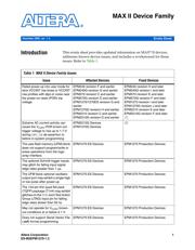
MAX II Device Family
utilization, clock frequency, and toggle factors. You can estimate the
I
CCINT
value by using the MAX II PowerPlay Early Power Estimator
and/or the Quartus
®
II Power Analyzer.
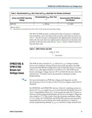
For DEV_OE use with EPM2210G and EPM1270G devices, you should
only use this feature if you can guarantee your design’s I
CCINT
is less than
the thresholds shown in Table 3. When enabled by the Quartus II
software, the DEV_OE feature does not use global resources but instead
uses dedicated circuitry to control the output enable on all design I/O
pins. For designs that cannot guarantee I
CCINT
is less the threshold, you
can use one of the four global signals to control device-wide output
enable (OE) control. Using a global signal OE instead of the DEV_OE pin
prevents the increase in POR trip voltage. The global signal OE requires
that you instantiate a tri-state buffer and connect an OE signal to all the
I/O pins in your design and assign the OE pin to a global signal in the
Quartus II software.
For in-system programming with EPM2210G and EPM1270G devices,
you should only use this feature if you can guarantee I
CCINT
is less than
the threshold shown in Table 3 for the running design immediately before
in-system programming begins. For designs that can operate with I
CCINT
greater than the threshold, you must either ensure within the system that
the AC activity of the EPM2210G or EPM1270G device is reduced before
in-system programming begins or instead use the real-time ISP feature.
The real-time ISP feature does not raise the POR brown-out trigger
voltage, thus it will not be susceptible to failed in-system programming
during high switching current conditions. Using real-time ISP means the
design continues to run during the in-system programming process.
f For more information on the real-time ISP feature, see the Using Real-time
ISP & ISP Clamp chapter of the MAX II Handbook.
EPM1270 ES
Device Issues
The following issues and support constraints affect the MAX II EPM1270
ES devices:
■ UFM block does not support program/write or erase operations
from the logic array interface
Table 3. EPM2210G & EPM1270G I
CCINT
Thresholds for Brown-Out Trigger
Voltage Issue with DEV_OE & In-System Programming
Device Current Threshold Units
EPM2210G 500 mA
EPM1270G 300 mA
器件 Datasheet 文档搜索
AiEMA 数据库涵盖高达 72,405,303 个元件的数据手册,每天更新 5,000 多个 PDF 文件
