Datasheet 搜索 > DC/DC转换器 > Fairchild(飞兆/仙童) > FAN53600AUC33X 数据手册 > FAN53600AUC33X 数据手册 4/16 页

¥ 2.586
FAN53600AUC33X 数据手册 - Fairchild(飞兆/仙童)
制造商:
Fairchild(飞兆/仙童)
分类:
DC/DC转换器
封装:
WLCSP-6
描述:
Fairchild Semiconductor### 非隔离直流/直流转换器,Fairchild Semiconductor
Pictures:
3D模型
符号图
焊盘图
引脚图
产品图
页面导航:

导航目录
FAN53600AUC33X数据手册
Page:
of 16 Go
若手册格式错乱,请下载阅览PDF原文件
© 2010 Fairchild Semiconductor Corporation www.fairchildsemi.com
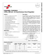
FAN53600 / FAN53610 • Rev. 1.4 3
FAN53600 / FAN53610 — 3 MHz, 600 mA / 1 A Synchronous Buck Regulator
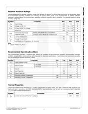
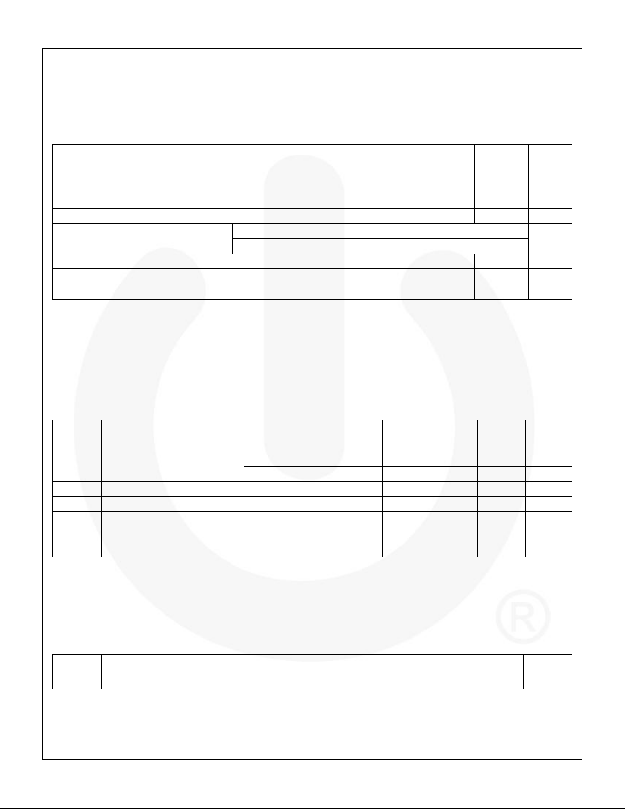
Absolute Maximum Ratings
Stresses exceeding the absolute maximum ratings may damage the device. The device may not function or be operable above
the recommended operating conditions and stressing the parts to these levels is not recommended. In addition, extended
exposure to stresses above the recommended operating conditions may affect device reliability. The absolute maximum ratings
are stress ratings only.
Symbol
Parameter
Min.
Max.
Unit
V
IN
Input Voltage
–0.3
7.0
V
V
SW
Voltage on SW Pin
–0.3
V
IN
+ 0.3
(3)
V
V
CTRL
EN and MODE Pin Voltage
–0.3
V
IN
+ 0.3
(3)
V
Other Pins
–0.3
V
IN
+ 0.3
(3)
V
ESD
Electrostatic Discharge
Protection Level
Human Body Model per JESD22-A114
2.0
kV
Charged Device Model per JESD22-C101
1.5
T
J
Junction Temperature
–40
+150
°C
T
STG
Storage Temperature
–65
+150
°C
T
L
Lead Soldering Temperature, 10 Seconds
+260
°C
Note:
3. Lesser of 7 V or V
IN
+0.3 V.
Recommended Operating Conditions
The Recommended Operating Conditions table defines the conditions for actual device operation. Recommended operating
conditions are specified to ensure optimal performance to the datasheet specifications. Fairchild does not recommend exceeding
them or designing to Absolute Maximum Ratings.
Symbol
Parameter
Min.
Typ.
Max.
Unit
V
CC
Supply Voltage Range
2.3
5.5
V
I
OUT
Output Current
FAN53600
0
600
mA
FAN53610
0
1
A
L
Inductor
1
µH
C
IN
Input Capacitor
2.2
µF
C
OUT
Output Capacitor
10
µF
T
A
Operating Ambient Temperature
–40
+85
°C
T
J
Operating Junction Temperature
–40
+125
°C
Thermal Properties
Junction-to-ambient thermal resistance is a function of application and board layout. This data is measured with four-layer 2s2p
boards (no vias) in accordance to JEDEC standard JESD51. Special attention must be paid not to exceed junction temperature
T
J(max)
at a given ambient temperature T
A
.
Symbol
Parameter
Typical
Unit
JA
Junction-to-Ambient Thermal Resistance
125
°C/W
器件 Datasheet 文档搜索
AiEMA 数据库涵盖高达 72,405,303 个元件的数据手册,每天更新 5,000 多个 PDF 文件
