Datasheet 搜索 > 卡边缘连接器 > Sullins > GEC08DRXI 数据手册 > GEC08DRXI 数据手册 2/2 页


¥ 22.04
GEC08DRXI 数据手册 - Sullins
制造商:
Sullins
分类:
卡边缘连接器
封装:
-
描述:
2.54mm P数:16
Pictures:
3D模型
符号图
焊盘图
引脚图
产品图
页面导航:
标记信息在P2
技术参数、封装参数在P1
导航目录
GEC08DRXI数据手册
Page:
of 2 Go
若手册格式错乱,请下载阅览PDF原文件
47
www.sullinscorp.com | 760-744-0125 | toll-free 888-774-3100 | fax 760-744-6081 | info@sullinscorp.com
Female Card Edge
Female Card Edge
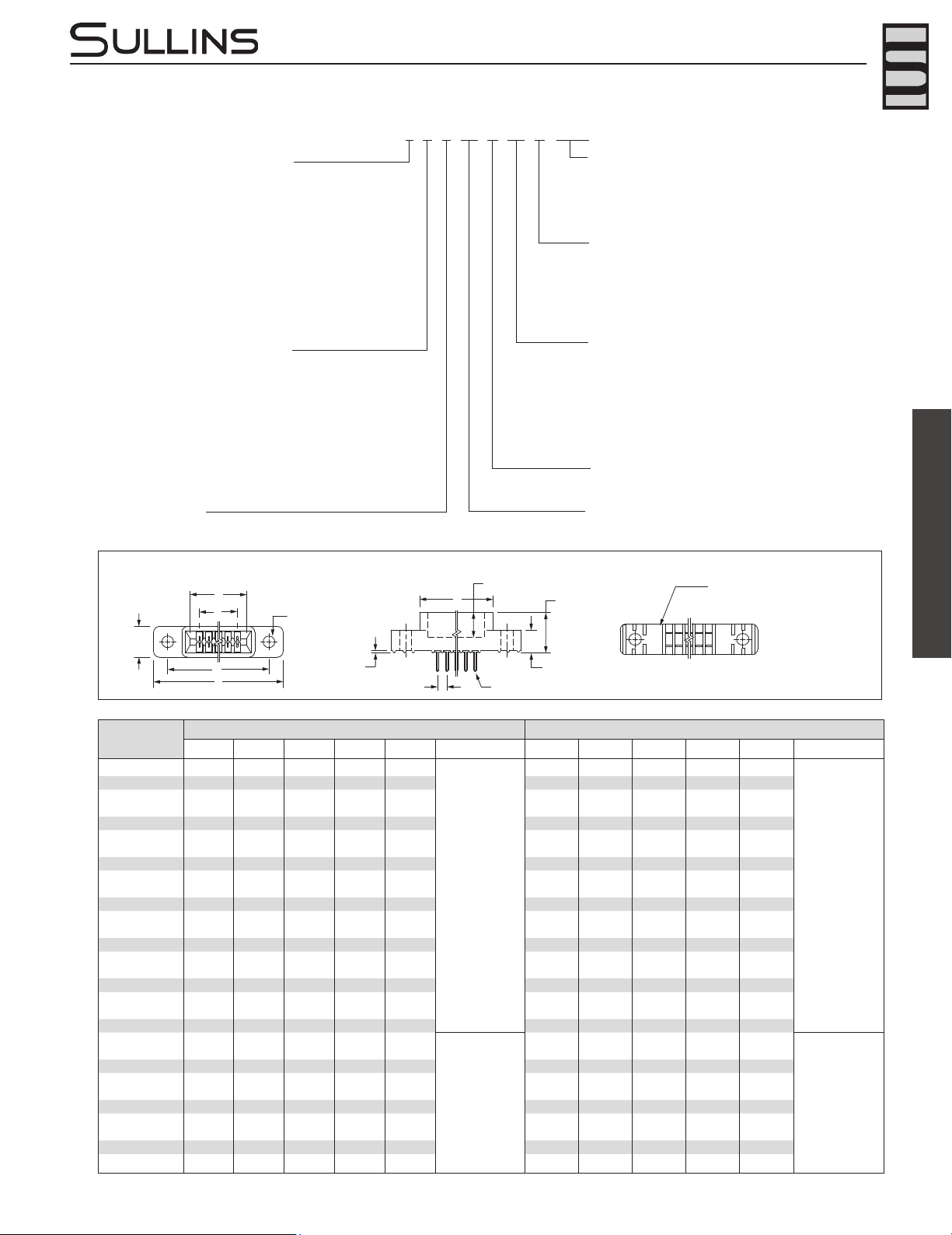
DIMENSIONS
Dimensionsin[]areinmillimeters,allothersareininches.
* Consult factory for availability.
.100” [2.54 mm] Contact Centers, .431” [10.95 mm] Insulator Height,
Dip Solder/Eyelet/Right Angle for .062”[1.57 mm] or .031” [0.79 mm] Mating PCB
Tolerances on non-critical dimensions may very slightly due to shrinkage differential per insulator material; Consult factory.
A
D
B
E
F
B 1 2 59 60 B
A 1 2 59 60 A
CONTACT MARKINGS
B 1 2 3 . . . 58 59 60 B
A 1 2 3 . . . 58 59 60 A
C
REFER TO
MOUNTING
STYLE
REFER TO TERMINATION TYPE
.100 [2.54] TYP.
.265 [6.73] INSERTION DEPTH
.431 [10.95]
.245 [6.22]
.025[0.64]
POSITIONS/
CONTACTS
INCHES MILLIMETERS
A±.008 B±.008 C±.015 D±.010 E±.020 F+.005/-.015 A±0.20 B±0.20 C±0.38 D±0.25 E±0.51 F+0.13/-0.38
04/08* 0.300 0.500 0.675 0.975 1.275
0.330
7.62 12.70 17.15 24.77 32.39
8.38
05/10 0.400 0.600 0.775 1.075 1.375 10.16 15.24 19.69 27.31 34.93
06/12 0.500 0.700 0.875 1.175 1.475 12.70 17.78 22.23 29.85 37.47
07/14 0.600 0.800 0.975 1.275 1.575 15.24 20.32 24.77 32.39 40.01
08/16 0.700 0.900 1.075 1.375 1.675 17.78 22.86 27.31 34.93 42.55
10/20 0.900 1.100 1.275 1.575 1.875 22.86 27.94 32.39 40.01 47.63
12/24 1.100 1.300 1.475 1.775 2.075 27.94 33.02 37.47 45.09 52.71
13/26 1.200 1.400 1.575 1.875 2.175 30.48 35.56 40.01 47.63 55.25
15/30 1.400 1.600 1.775 2.075 2.375 35.56 40.64 45.09 52.71 60.33
17/34 1.600 1.800 1.975 2.275 2.575 40.64 45.72 50.17 57.79 65.41
18/36 1.700 1.900 2.075 2.375 2.675 43.18 48.26 52.71 60.33 67.95
19/38 1.800 2.000 2.175 2.475 2.775 45.72 50.80 55.25 62.87 70.49
20/40 1.900 2.100 2.275 2.575 2.875 48.26 53.34 57.79 65.41 73.03
22/44 2.100 2.300 2.475 2.775 3.075 53.34 58.42 62.87 70.49 78.11
23/46* 2.200 2.400 2.575 2.875 3.175 55.88 60.96 65.41 73.03 80.65
25/50 2.400 2.600 2.775 3.075 3.375 60.96 66.04 70.49 78.11 85.73
26/52 2.500 2.700 2.875 3.175 3.475 63.50 68.58 73.03 80.65 88.27
28/56 2.700 2.900 3.075 3.375 3.675 68.58 73.66 78.11 85.73 93.35
30/60 2.900 3.100 3.275 3.575 3.875 73.66 78.74 83.19 90.81 98.43
31/62 3.000 3.200 3.375 3.675 3.975 76.20 81.28 85.73 93.35 100.97
35/70 3.400 3.600 3.775 4.075 4.375
0.400
86.36 91.44 95.89 103.51 111.13
10.16
36/72 3.500 3.700 3.875 4.175 4.475 88.90 93.98 98.43 106.05 113.67
40/80 3.900 4.100 4.275 4.575 4.875 99.06 104.14 108.59 116.21 123.83
43/86 4.200 4.400 4.575 4.875 5.175 106.68 111.76 116.21 123.83 131.45
44/88 4.300 4.500 4.675 4.975 5.275 109.22 114.30 118.75 126.37 133.99
49/98 4.800 5.000 5.175 5.475 5.775 121.92 127.00 131.45 139.07 146.69
50/100 4.900 5.100 5.275 5.575 5.875 124.46 129.54 133.99 141.61 149.23
52/104* 5.100 5.300 5.475 5.775 6.075 129.54 134.62 139.07 146.69 154.31
60/120 5.900 6.100 6.275 6.575 6.875 149.86 154.94 159.39 167.01 174.63
65/130 6.400 6.600 6.775 7.075 7.375 162.56 167.64 172.09 179.71 187.33
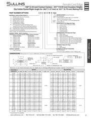
MATERIALS (INSULATOR/CONTACT)
CONTACT CENTERS
C = .100”[2.54mm]
H = .125”[3.18mm]ClearanceHoles
N = NoMounting
B = OpenCardslot
S = SideMounting
I = ThreadedInsert
F = FloatingBobbin
OMITFORSTANDARD
-S13 = CardExtenderAccepts.062”[1.57mm]PCB
(RE,RT,RYTerminationsOnly)
-S734 = .031”±.006”[0.79mm±0.15mm]MatingPCB
-S924 = SurfaceMount
MODIFICATIONS (ConsultFactory)
D = Dual
H = HalfLoaded
READOUT (Opposite Page)
MOUNTING STYLE (Opposite Page)
RA = RightAngle
RE = Eyelet(Standard)
TE = Eyelet(OverallPlatedOnly)
**ET,RT = .140”[3.56mm]X.200”[5.08mm]DipSolder
**EY,RY = .140”[3.56mm]X.440”[11.19mm]DipSolder
RX = .200”[5.08mm]X.185”[4.70mm]DipSolder
RJ = .250”[6.35mm]X.165”[4.19mm]DipSolder
SX = .110”[2.79mm]CenteredDipSolder
TERMINATION TYPE (Opposite Page)
NUMBER OF CONTACT POSITIONS
SeeChartBelow
**'ET'&'EY'Onlyavailablein'B'&'C'Platingcode
E = PBT/PhosphorBronze(Standard)
R = PPS/PhosphorBronze
G = PA9T/PhosphorBronze
H = PBT/BerylliumCopper
A = PPS/BerylliumCopper
J = PA9T/BerylliumCopper
* F = PPS/Spinodal(OverallGoldPlatingOnly)
ConsultFactoryforSpecialSolderingGuidelines
*C = PPS/BerylliumNickel(OverallGoldPlatingOnly)
*W = PEEK/BerylliumNickel(OverallGoldPlatingOnly)
*Consultfactoryforavailability.
RefertoPage7forOperating/ProcessingTemperatures
Contact Surface Termination
B = .000010”Gold .000100”PureTin,Matte
C = .000030”Gold .000100”PureTin,Matte
G = .000010”Gold .000005”Gold
Y = .000030”Gold .000005”Gold
Contact Surface Overall Plating
S = .000010”Gold .000010”Gold
M = .000030”Gold .000010”Gold
E = .000100”PureTin,Matte .000100”PureTin,Matte
E B C 43 D RE H - Sxxx
CONTACT FINISH - RoHS Compliant
All platings are Lead Free and have .000050” Nickel underplate
PART NUMBER OPTIONS
器件 Datasheet 文档搜索
AiEMA 数据库涵盖高达 72,405,303 个元件的数据手册,每天更新 5,000 多个 PDF 文件
