Datasheet 搜索 > 电容 > muRata(村田) > GRM188R61C475KE11J 数据手册 > GRM188R61C475KE11J 数据手册 2/29 页
 器件3D模型
¥ 0.535
GRM188R61C475KE11J 数据手册 - muRata(村田)
制造商:
muRata(村田)
分类:
电容
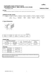
封装:
0603
Pictures:
3D模型
符号图
焊盘图
引脚图
产品图
页面导航:
导航目录
GRM188R61C475KE11J数据手册
Page:
of 29 Go
若手册格式错乱,请下载阅览PDF原文件
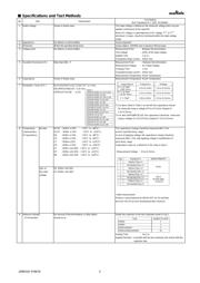
■ Specifications and Test Methods
No
1 Rated Voltage Shown in Rated value. The rated voltage is defined as the maximum voltage which may be
applied continuously to the capacitor.
When AC voltage is superimposed on DC voltage, V
P-P
or V
O-P
,
whichever is larger, should be maintained within the rated voltage
range.
2 Appearance No defects or abnormalities. Visual inspection.
3 Dimension Within the specified dimensions. Using calipers. (GRM02 size is based on Microscope)
4 Voltage proof No defects or abnormalities.
Measurement Point :
Between the terminations
Test Voltage :
250% of the rated voltage
Applied Time :
1 to 5 s
Charge/discharge current :
50mA max.
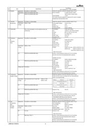
5 Insulation Resistance(I.R.)
Measurement Point : Between the terminations
Measurement Voltage :
DC Rated Voltage
Charging Time :
1 min
Charge/discharge current :
50mA max.
Measurement Temperature :
Room Temperature
6 Capacitance Shown in Rated value.
Measurement Temperature :
Room Temperature
7 Dissipation Factor (D.F.) B1,R1,B3,R6,R7,C6,C7,C8,E7,D7 : 0.1 max.
D8,GRM31CR60J107 : 0.15 max
GRM31CR71E106 : 0.125
max
*1 For items listed in Table 1 on the left, the capacitance should
be measured using a voltage of 0.5+/-0.1Vrms instead of
1.0+/-0.2Vrms.
*2 For item GRM188R70J105, the capacitance should be measured
using a voltage of 1.0+/-0.2Vrms instead of 0.5+/-0.1Vrms.
8
Temperature No bias B1,B3 : Within +/-10% (-25°C to +85°C) The capacitance change should be measured after 5 min.
Characteristics R1,R7 : Within +/-15% (-55°C to +125°C) at each specified temp. stage.
of Capacitance R6 : Within +/-15% (-55°C to +85°C) In case of applying voltage, the capacitance change should be
C6 : Within +/-22% (-55°C to +85°C) measured after 1 min. with applying voltage in equilibration of
C7 : Within+/-22% (-55°C to +125°C) each temp. stage.
C8 : Within +/-22% (-55°C to +105°C) Capacitance value as a reference is the value in step 3.
E7 : Within +22/-56% (-55°C to +125°C)
D7 : Within +22/-33% (-55°C to +125°C) · Measurement Voltage : 0.5+/-0.1Vrms
D8 : Within +22/-33% (-55°C to +105°C)
50% of
B1: Within +10/-30%
the rated
R1: Within +15/-40%
voltage
・Initial measurement
Perform a heat treatment at 150+0/-10°C for 1h and then
let sit for 24+/-2h at room temperature,then measure.
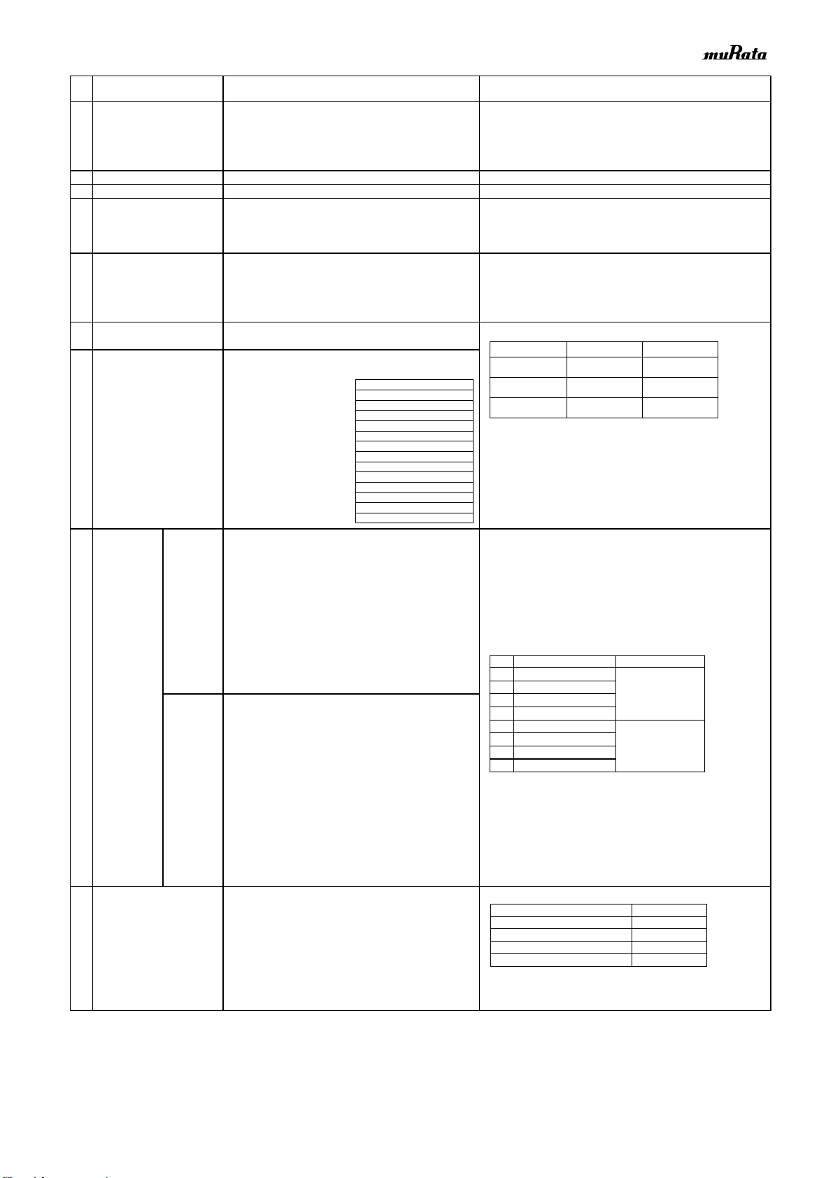
9 Adhesive Strength No removal of the terminations or other defect Solder the capacitor on the test substrate shown in Fig.3.
of Termination should occur.
Holding Time : 10+/-1s
Applied Direction : In parallel with the test substrate and vertical with the
capacitor side.
Test Method
(Ref. Standard:JIS C 5101, IEC60384)
Item
Specification
Type Applied Force(N)
GRM02 1
GRM03 2
GRM15/GRM18 5
GRM21/GRM31/GRM32 10
c
b
a
Solder Resist
Chip Capacitor
Land
Step
Temperature(C)
Applying Voltage(VDC)
1
Reference Temp.+/-2
No bias
2
Min.Operating Temp. +/-3
3
Reference Temp. +/-2
4
Max.Operating Temp. +/-3
5
Reference Temp. +/-2
50% of
the rated voltage
(For B1,R1)
6
Min.Operating Temp. +/-3
7
Reference Temp. +/-2
8
Max.Operating Temp.+/-3
*Table 1
GRM033 B3/R6 1A 123 to 823
GRM033 B3/R6 1A 104
GRM155 B3/R6 1A 124 to 105
GRM185 B3/R6 1C/1A 105
GRM185 C8/D7 1A 105
GRM188 B3/R6 1C/1A 225
GRM188 R7/C8/D7 1A 225
GRM188 B3/R6 1A 335
GRM219 B3/R6 1C/1A 475
GRM219 C8 1A 475
GRM219 B3/R6 1A 106
GRM21B B3/R6 1C/1A 106
GRM21B R7/C8 1A 106
GRM319 B3/R6 1C/1A 106
Capacitance
Frequency
Voltage
*1 C≦
(10V min.)
1.0+/-0.1kHz
1.0+/-0.2Vrms
*2 C≦
(6.3V max.)
1.0+/-0.1kHz
0.5+/-0.1Vrms
C>
120+/-24Hz
0.5+/-0.1Vrms
JEMCGS-01861B 2
器件 Datasheet 文档搜索
AiEMA 数据库涵盖高达 72,405,303 个元件的数据手册,每天更新 5,000 多个 PDF 文件
