Datasheet 搜索 > 陶瓷电容 > muRata(村田) > GRM21BR60J476ME15L 数据手册 > GRM21BR60J476ME15L 数据手册 3/30 页
 器件3D模型
¥ 0.145
GRM21BR60J476ME15L 数据手册 - muRata(村田)
制造商:
muRata(村田)
分类:
陶瓷电容
封装:
0805
描述:
MURATA GRM21BR60J476ME15L 多层陶瓷电容器, 表面贴装, GRM系列, 47 µF, ± 20%, X5R, 6.3 V, 0805 [2012 公制]
Pictures:
3D模型
符号图
焊盘图
引脚图
产品图
页面导航:
导航目录
GRM21BR60J476ME15L数据手册
Page:
of 30 Go
若手册格式错乱,请下载阅览PDF原文件
No
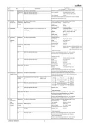
10 Vibration Appearance No defects or abnormalities. Solder the capacitor on the test substrate shown in Fig.3.
Capacitance Within the specified initial value.
Kind of Vibration :
A simple harmonic motion
D.F. Within the specified initial value. 10Hz to 55Hz to 10Hz (1min)
Total amplitude :
1.5mm
This motion should be applied for a period of 2h in each 3 mutually
perpendicular directions(total of 6h).
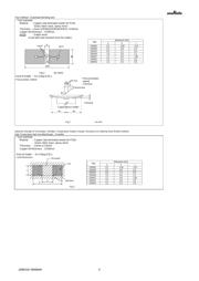
11 Substrate Appearance No defects or abnormalities. Solder the capacitor on the test substrate shown in Fig.1.
Bending test
Capacitance Within +/-10% Pressurization method : Shown in Fig.2
Change Flexure : 1mm
Holding Time :
5+/-1s
Soldering Method :
Reflow soldering
12 Solderability
95% of the terminations is to be soldered evenly and
Test Method :
Solder bath method
continuously. Flux Solution of rojin ethanol 25(wt)%
Preheat :
80℃ to 120℃ for 10s to 30s
Solder : Sn-3.0Ag-0.5Cu
Solder Temp. :
245+/-5℃
Immersion time
:
2+/-0.5s
13
Resistance Appearance No defects or abnormalities. <GRM03 size min.>
to Test Method : Solder bath method
Soldering Solder : Sn-3.0Ag-0.5Cu
Heat Solder Temp. :
270+/-5℃
Immersion time
:
10+/-0.5s
Capacitance Within +/-15% Exposure Time : 24+/-2h
Change Preheat : GRM31 size max.: 120℃ to 150℃ for 1 min
GRM32 size : 100℃ to 120℃ for 1 min
and 170℃ to 200℃ for 1 min
· Initial measurement
D.F. Within the specified initial value. Perform a heat treatment at 150+0/-10°C for 1h and then
let sit for 24+/-2h at room temperature,then measure.
<GRM02 size only>
Test Method : Reflow soldering (hot plate)
I.R. Within the specified initial value. Solder : Sn-3.0Ag-0.5Cu
Solder Temp. :
270+/-5℃
Reflow Time : 10+/-0.5s
Test Substrate : Glass epoxy PCB
Voltage proof No defects. Exposure Time : 24+/-2h
Preheat :
120℃ to 150℃ for 1 min
· Initial measurement
Perform a heat treatment at 150+0/-10°C for 1h and then
let sit for 24+/-2h at room temperature,then measure.
14
Temperature
Appearance No defects or abnormalities. Solder the capacitor on the test substrate shown in Fig.3.
Sudden Change
Perform the five cycles according to the four heat treatments
shown in the following table.
Capacitance B1,R1,B3,R6,R7,C6,C7,C8,D7,D8 : Within +/-7.5%
Change E7 : Within +/-30%
D.F. Within the specified initial value.
I.R. Within the specified initial value. Exposure Time : 24+/-2h
· Initial measurement
Voltage proof No defects. Perform a heat treatment at 150+0/-10°C for 1h and then
let sit for 24+/-2h at room temperature,then measure.
· GRM188B30J106M Measurement after test:
Perform a heat treatment at 150+0/-10°C for 1h and then
let sit for 24+/-2h at room temperature,then measure.
15
High
Appearance No defects or abnormalities. Solder the capacitor on the test substrate shown in Fig.3.
Temperature
Test Temperature :
40+/-2℃
High
Test Humidity :
90%RH to 95%RH
Humidity Capacitance Within +/-12.5%
Test Time :
500+/-12h
(Steady) Change
Applied Voltage :
DC Rated Voltage
Charge/discharge current : 50mA max.
D.F. 0.2 max.
Exposure Time :
24+/-2h
· Initial measurement
I.R.
∙ F
Perform a heat treatment at 150+0/-10°C for 1h and then
let sit for 24+/-2h at room temperature,then measure.
· Measurement after test
Perform a heat treatment at 150+0/-10°C for 1h and then
let sit for 24+/-2h at room temperature,then measure.
Item
Specification
Test Method
(Ref. Standard:JIS C 5101, IEC60384)
Type Applied Force(N)
GRM02 1
GRM03 2
GRM15/GRM18 5
GRM21/GRM31/GRM32 10
c
b
a
Solder Resist
Chip Capacitor
Land
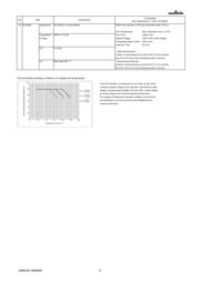
These Part Numbers are designed for use in the circuits where
continuous applied voltage to the capacitor is derated than rated
voltage, and guarantee Durability Test with 100% × rated voltage
as testing voltage at the maximum operating temperature.
The voltage and temperature derating conditions on the left are
recommended for use to ensure the same reliability level as
normal specification.
Step
Temp.(C)
Time
(min)
1
Min.Operating Temp.+0/-3
30+/-3
2
Room Temp
2 to 3
3
Max.Operating Temp.+3/-0
30+/-3
4
Room Temp
2 to 3
JEMCGS-00499AK 3
器件 Datasheet 文档搜索
AiEMA 数据库涵盖高达 72,405,303 个元件的数据手册,每天更新 5,000 多个 PDF 文件
