Datasheet 搜索 > MOS管 > Vishay Semiconductor(威世) > IRLL110PBF 数据手册 > IRLL110PBF 数据手册 1/8 页

¥ 1.332
IRLL110PBF 数据手册 - Vishay Semiconductor(威世)
制造商:
Vishay Semiconductor(威世)
分类:
MOS管
封装:
SOT-223
描述:
VISHAY IRLL110PBF 晶体管, MOSFET, N沟道, 1.5 A, 100 V, 540 mohm, 5 V, 2 V
Pictures:
3D模型
符号图
焊盘图
引脚图
产品图
页面导航:
封装尺寸在P7
标记信息在P7
技术参数、封装参数在P1
电气规格在P2
导航目录
IRLL110PBF数据手册
Page:
of 8 Go
若手册格式错乱,请下载阅览PDF原文件
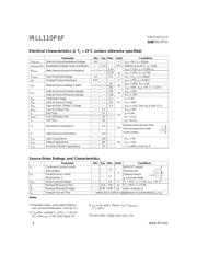
Parameter Max. Units
I
D
@ Tc = 25°C Continuous Drain Current, V
GS
@ 5.0 V 1.5
I
D
@ Tc = 100°C Continuous Drain Current, V
GS
@ 5.0 V 0.93
I
DM
Pulsed Drain Current 12
P
D
@Tc = 25°C Power Dissipation 3.1
P
D
@T
A
= 25°C Power Dissipation (PCB Mount)** 2..0 W
Linear Derating Factor 0.025
Linear Derating Factor (PCB Mount)** 0.017 W/°C
V
GS
Gate-to-Source Voltage -/+10 V
E
AS
Single Pulse Avalanche Energy 50 mJ
I
AR
Avalanche Current 1.5 A
E
AR
Repetitive Avalanche Energy 0.31 mJ
dv/dt Peak Diode Recovery dv/dt 5.5 V/ns
T
J,
T
STG
Junction and Storage Temperature Range -55 to + 150 °C
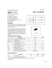
IRLL110PbF
HEXFET
®
Power MOSFET
PD - 95222
S
D
G
V
DSS
= 100V
R
DS(on)
= 0.54Ω
I
D
= 1.5A
Third Generation HEXFETs from International Rectifier
provide the designer with the best combination of fast
switching, ruggedized device design, low on-resistance
and cost-effectiveness.
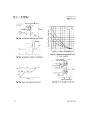
The SOT-223 package is designed for surface-mount using
vapor phase, infra red, or wave soldering techniques. Its
unique package design allows for easy automatic pick-and-
place as with other SOT or SOIC packages but has the
added advantage of improved thermal performance due to
an enlarged tab for heatsinking. Power dissipation of
grreater than 1.25W is possible in a typical surface mount
application.
04/27/04
Description
l Surface Mount
l Available in Tape & Reel
l Dynamic dv/dt Rating
l Repetitive Avalanche Rated
l Logic-Level Gate Drive
l RDS(on)Specified at VGS= 4V & 5V
l Fast Switching
l Lead-Free
SOT-223
** When mounted on 1'' square PCB (FR-4 or G-10 Material).
For recommended footprint and soldering techniques refer to application note #AN-994.
Parameter Typ. Max. Units
R
θJC
Junction-to-PCB ––– 40
R
θJA
Junction-to-Ambient. (PCB Mount)** ––– 60
Thermal Resistance
°C/W
Absolute Maximum Ratings
A
www.irf.com 1
Soldewring Temperature, for 10 seconds
300 (1.6mm from case)
器件 Datasheet 文档搜索
AiEMA 数据库涵盖高达 72,405,303 个元件的数据手册,每天更新 5,000 多个 PDF 文件
