Datasheet 搜索 > 接口芯片 > Microchip(微芯) > LAN9500AI-ABZJ-TR 数据手册 > LAN9500AI-ABZJ-TR 数据手册 25/213 页
 器件3D模型
¥ 15.679
LAN9500AI-ABZJ-TR 数据手册 - Microchip(微芯)
制造商:
Microchip(微芯)
分类:
接口芯片
封装:
QFN-56
描述:
以太网控制器, 100 Mbps, IEEE 802.3, IEEE 802.3u, 3 V, 3.6 V, QFN, 56 引脚
Pictures:
3D模型
符号图
焊盘图
引脚图
产品图
页面导航:
引脚图在P11P22P111Hot
典型应用电路图在P112
原理图在P7P25P101P103
封装尺寸在P207
封装信息在P1P207P208P211
功能描述在P1P25P58
技术参数、封装参数在P193P195P204P205P206
应用领域在P1P168
导航目录
LAN9500AI-ABZJ-TR数据手册
Page:
of 213 Go
若手册格式错乱,请下载阅览PDF原文件
2010 - 2015 Microchip Technology Inc. DS00001875A-page 25
LAN950x
5.0 FUNCTIONAL DESCRIPTION
5.1 Functional Overview
The LAN950x USB 2.0 to 10/100 Ethernet Controller consists of the following major functional blocks:
• USB PHY
• USB 2.0 Device Controller (UDC)
• FIFO Controller (FCT) and Associated SRAM
• 10/100 Ethernet MAC
• 10/100 Internal Ethernet PHY
• IEEE 1149.1 Tap Controller
• EEPROM Controller (EPC)
The following sections discuss the features of each block. A block diagram of the device is shown in FIGURE 2-1:
LAN950x Block Diagram on page 7.
5.2 USB PHY
The USB PHY has the USB interface on one end, and connects to the USB 2.0 Device Controller on the other. The
Parallel-to-serial/serial-to-parallel conversion, bit stuffing, and NRZI coding / decoding are handled in the PHY block.
The PHY is capable of operating in the USB 1.1 and 2.0 modes.
5.3 USB 2.0 Device Controller (UDC)
The USB functionality in the device consists of five major parts. The USB PHY (discussed in Section 5.2), UCB (USB
Common Block), UDC (USB Device Controller), URX (USB Bulk Out Receiver), UTX (USB Bulk In Receiver), and CTL
(USB Control Block). They are represented as the USB PHY and UDC, collectively, in FIGURE 2-1: LAN950x Block
Diagram on page 7.
The UCB generates various clocks, including the system clocks of the device. The URX and UTX implement the Bulk
Out and Bulk In endpoints respectively. The CTL manages control and interrupt endpoints.
The UDC is a USB low-level protocol interpreter. The UDC controls the USB bus protocol, packet generation/extraction,
PID/Device ID parsing, and CRC coding/decoding with autonomous error handling. It is capable of operating either in
USB 1.1 or 2.0 compliant modes. It has autonomous protocol handling functions like stall condition clearing on setup
packets, suspend/resume/reset conditions, and remote wakeup. It also autonomously handles error conditions such as
retry for CRC errors, Data toggle errors, and generation of NYET, STALL, ACK and NACK, depending on the endpoint
buffer status.
The UDC is configured to support one configuration, one interface, one alternate setting, and four endpoints.
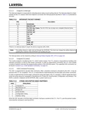
5.3.1 SUPPORTED ENDPOINTS
Table 5-1lists the supported endpoints. The following subsections discuss these endpoints in detail.
The URX and UTX implement the Bulk Out and Bulk In endpoints, respectively. The CTL manages the Control and Inter-
rupt endpoints.
TABLE 5-1: SUPPORTED ENDPOINTS
Endpoint
Number
Description
0 Control Endpoint
1 Bulk In Endpoint
2 Bulk Out Endpoint
3 Interrupt Endpoint
器件 Datasheet 文档搜索
AiEMA 数据库涵盖高达 72,405,303 个元件的数据手册,每天更新 5,000 多个 PDF 文件
