Datasheet 搜索 > DC/DC转换器 > TI(德州仪器) > LM22678QTJE-ADJ/NOPB 数据手册 > LM22678QTJE-ADJ/NOPB 数据手册 10/23 页

¥ 121.347
LM22678QTJE-ADJ/NOPB 数据手册 - TI(德州仪器)
制造商:
TI(德州仪器)
分类:
DC/DC转换器
封装:
TO-263-7
描述:
开关稳压器 5A SD Vtg Reg
Pictures:
3D模型
符号图
焊盘图
引脚图
产品图
页面导航:
引脚图在P4Hot
原理图在P1P8
封装尺寸在P2P3P20
型号编码规则在P2
封装信息在P2P3
功能描述在P1
技术参数、封装参数在P5P6
应用领域在P1P23
电气规格在P5P6P10P12P14P16
导航目录
LM22678QTJE-ADJ/NOPB数据手册
Page:
of 23 Go
若手册格式错乱,请下载阅览PDF原文件
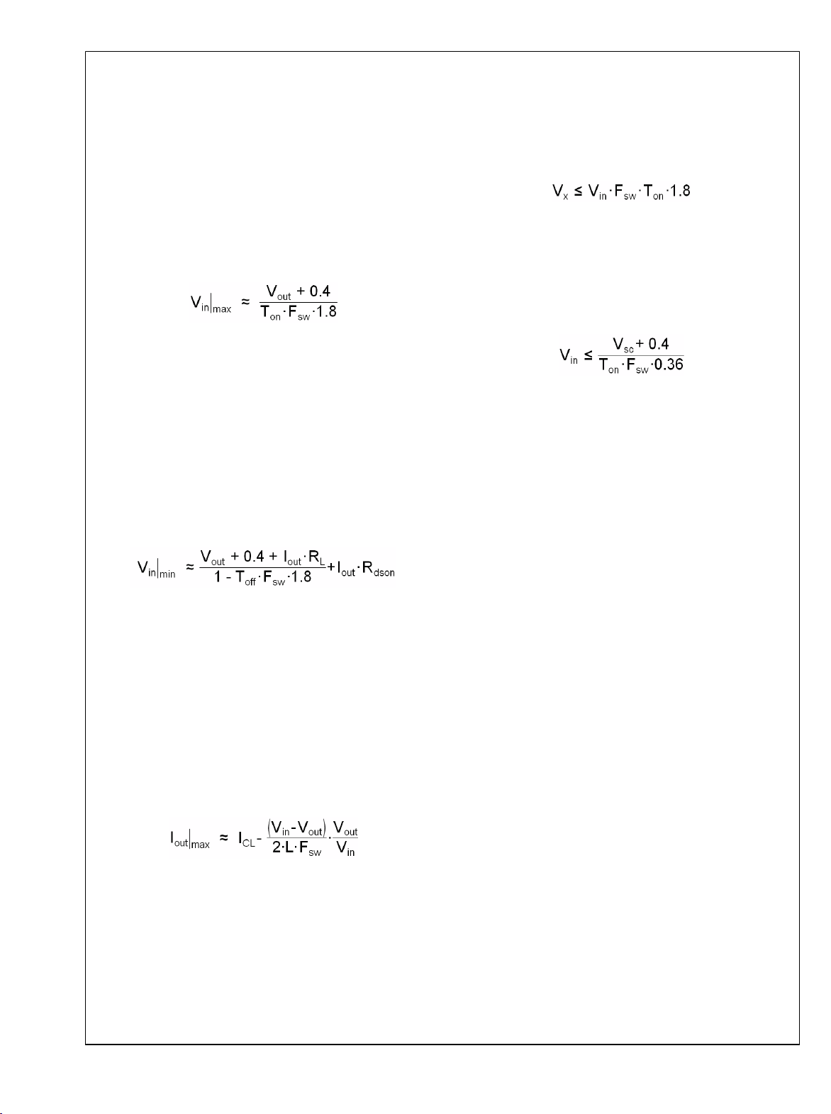
Duty-Cycle Limits
Ideally the regulator would control the duty cycle over the full
range of zero to one. However due to inherent delays in the
circuitry, there are limits on both the maximum and minimum
duty cycles that can be reliably controlled. This in turn places
limits on the maximum and minimum input and output volt-
ages that can be converted by the LM22670. A minimum on-
time is imposed by the regulator in order to correctly measure
the switch current during a current limit event. A minimum off-
time is imposed in order the re-charge the bootstrap capaci-
tor. The following equation can be used to determine the
approximate maximum input voltage for a given output volt-
age:
Where F
sw
is the switching frequency and T
ON
is the minimum
on-time; both found in the Electrical Characteristics table. If
the frequency adjust feature is used, that value should be
used for F
sw
. Nominal values should be used. The worst case
is lowest output voltage, and highest switching frequency. If
this input voltage is exceeded, the regulator will skip cycles,
effectively lowering the switching frequency. The conse-
quences of this are higher output voltage ripple and a degra-
dation of the output voltage accuracy.
The second limitation is the maximum duty cycle before the
output voltage will "dropout" of regulation. The following equa-
tion can be used to approximate the minimum input voltage
before dropout occurs:
The values of T
OFF
and R
DS(ON)
are found in the Electrical
Characteristics table. The worst case here is highest switch-
ing frequency and highest load. In this equation, R
L
is the D.C.
inductor resistance. Of course, the lowest input voltage to the
regulator must not be less than 4.5V (typ.).
Current Limit
The LM22670 has current limiting to prevent the switch cur-
rent from exceeding safe values during an accidental over-
load on the output. This peak current limit is found in the
Electrical Characteristics table under the heading of I
CL
. The
maximum load current that can be provided, before current
limit is reached, is determined from the following equation:
Where L is the value of the power inductor.
When the LM22670 enters current limit, the output voltage will
drop and the peak inductor current will be fixed at I
CL
at the
end of each cycle. The switching frequency will remain con-
stant while the duty cycle drops. The load current will not
remain constant, but will depend on the severity of the over-
load and the output voltage.
For very severe overloads ("short-circuit"), the regulator
changes to a low frequency current foldback mode of opera-
tion. The frequency foldback is about 1/5 of the nominal
switching frequency. This will occur when the current limit
trips before the minimum on-time has elapsed. This mode of
operation is used to prevent inductor current "run-away", and
is associated with very low output voltages when in overload.
The following equation can be used to determine what level
of output voltage will cause the part to change to low frequen-
cy current foldback:
Where F
sw
is the normal switching frequency and V
in
is the
maximum for the application. If the overload drives the output
voltage to less than or equal to V
x
, the part will enter current
foldback mode. If a given application can drive the output
voltage to ≤V
x
, during an overload, then a second criterion
must be checked. The next equation gives the maximum input
voltage, when in this mode, before damage occurs:
Where V
sc
is the value of output voltage during the overload
and F
sw
is the normal switching frequency. If the input volt-
age should exceed this value, while in foldback mode, the
regulator and/or the diode may be damaged. It is important
to note that the voltages in these equations are measured at
the inductor. Normal trace and wiring resistance will cause the
voltage at the inductor to be higher than that at a remote load.
Therefore, even if the load is shorted with zero volts across
its terminals, the inductor will still see a finite voltage. It is this
value that should be used for V
x
and V
sc
in the calculations.
In order to return from foldback mode, the load must be re-
duced to a value much lower than that required to initiate
foldback. This load "hysteresis" is a normal aspect of any type
of current limit foldback associated with voltage regulators.
If the frequency synchronization feature is used, the current
limit frequency fold-back is not operational, and the system
may not survive a hard short-circuit at the output.
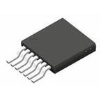
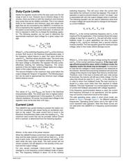
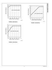
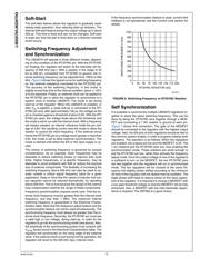
The safe operating areas, when in short circuit mode, are
shown in Figure 3 through Figure 5 , for different switching
frequencies. Operating points below and to the right of the
curve represent safe operation. Note that these curves are
not valid when the LM22670 is in frequency synchronization
mode.
www.ti.com 10
LM22670/LM22670Q
器件 Datasheet 文档搜索
AiEMA 数据库涵盖高达 72,405,303 个元件的数据手册,每天更新 5,000 多个 PDF 文件
