Datasheet 搜索 > 比较器 > TI(德州仪器) > LM2903M 数据手册 > LM2903M 数据手册 11/29 页
 器件3D模型
¥ 3.291
LM2903M 数据手册 - TI(德州仪器)
制造商:
TI(德州仪器)
分类:
比较器
封装:
SOIC-8
描述:
TEXAS INSTRUMENTS LM2903M 模拟比较器, 双路, 精度, 2, 1.5 µs, ± 1V 至 ± 18V, SOIC, 8 引脚
Pictures:
3D模型
符号图
焊盘图
引脚图
产品图
页面导航:
引脚图在P3Hot
典型应用电路图在P11P12P13P14P15P16P17
原理图在P1P10
封装尺寸在P20P21P23P24
标记信息在P20P21
封装信息在P19P20P21P22P23P24
技术参数、封装参数在P4
应用领域在P1P11P12P13P14P15P16P17P29
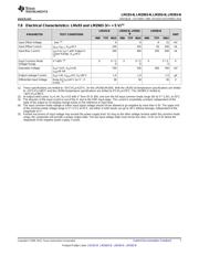
电气规格在P4P5P6P7
导航目录
LM2903M数据手册
Page:
of 29 Go
若手册格式错乱,请下载阅览PDF原文件
LM193-N
,
LM2903-N
,
LM293-N
,
LM393-N
www.ti.com
SNOSBJ6F –OCTOBER 1999–REVISED DECEMBER 2014
9 Application and Implementation
NOTE
Information in the following applications sections is not part of the TI component
specification, and TI does not warrant its accuracy or completeness. TI’s customers are
responsible for determining suitability of components for their purposes. Customers should
validate and test their design implementation to confirm system functionality.
9.1 Application Information
The LM193 series are high gain, wide bandwidth devices which, like most comparators, can easily oscillate if the
output lead is inadvertently allowed to capacitively couple to the inputs via stray capacitance. This shows up only
during the output voltage transition intervals as the comparator change states. Power supply bypassing is not
required to solve this problem. Standard PC board layout is helpful as it reduces stray input-output coupling.
Reducing the input resistors to < 10 kΩ reduces the feedback signal levels and finally, adding even a small
amount (1.0 to 10 mV) of positive feedback (hysteresis) causes such a rapid transition that oscillations due to
stray feedback are not possible. Simply socketing the IC and attaching resistors to the pins will cause input-
output oscillations during the small transition intervals unless hysteresis is used. If the input signal is a pulse
waveform, with relatively fast rise and fall times, hysteresis is not required.
All input pins of any unused comparators should be tied to the negative supply.
The bias network of the LM193 series establishes a drain current which is independent of the magnitude of the
power supply voltage over the range of from 2.0 V
DC
to 30 V
DC
.
The differential input voltage may be larger than V
+
without damaging the deviceTypical Applications . Protection
should be provided to prevent the input voltages from going negative more than −0.3 V
DC
(at 25°C). An input
clamp diode can be used as shown in Typical Applications .
The output of the LM193 series is the uncommitted collector of a grounded-emitter NPN output transistor. Many
collectors can be tied together to provide an output OR'ing function. An output pullup resistor can be connected
to any available power supply voltage within the permitted supply voltage range and there is no restriction on this
voltage due to the magnitude of the voltage which is applied to the V
+
terminal of the LM193 package. The
output can also be used as a simple SPST switch to ground (when a pullup resistor is not used). The amount of
current which the output device can sink is limited by the drive available (which is independent of V
+
) and the β
of this device. When the maximum current limit is reached (approximately 16mA), the output transistor will come
out of saturation and the output voltage will rise very rapidly. The output saturation voltage is limited by the
approximately 60Ω r
SAT
of the output transistor. The low offset voltage of the output transistor (1.0mV) allows the
output to clamp essentially to ground level for small load currents.
9.2 Typical Applications
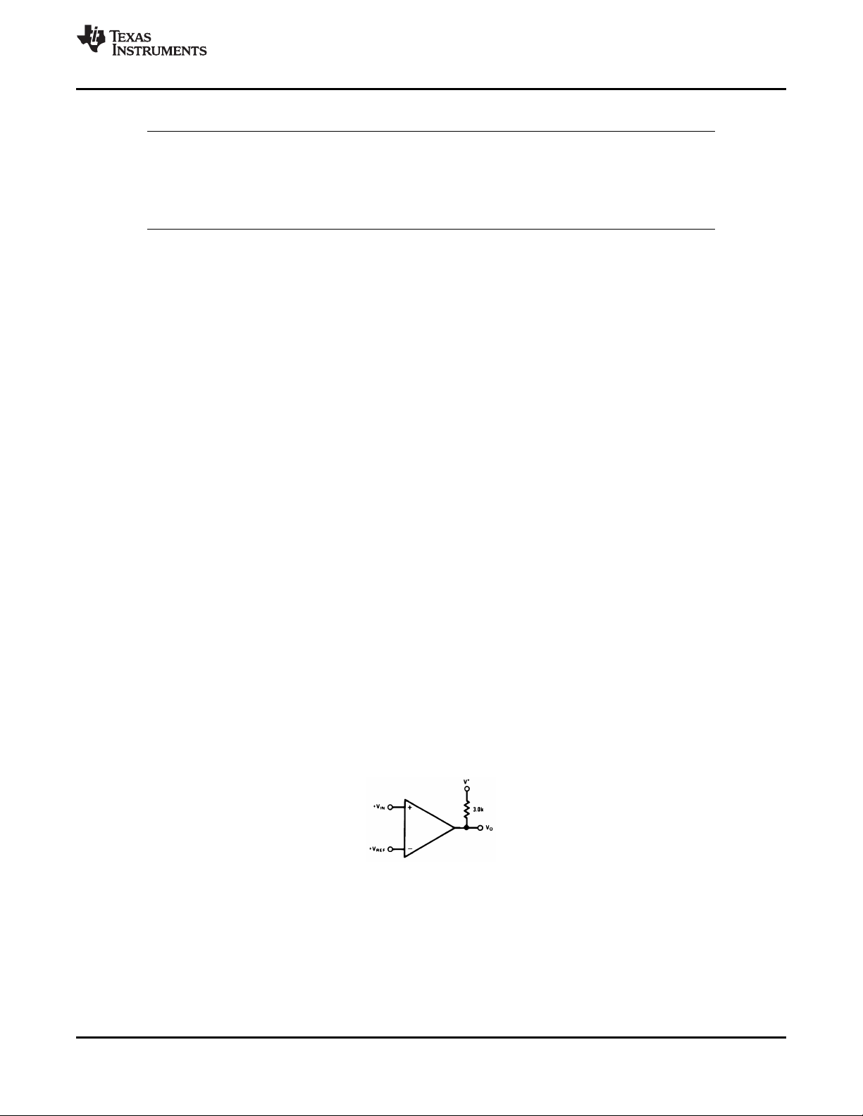
9.2.1 Basic Comparator
Figure 12. Basic Comparator
9.2.1.1 Design Requirements
The basic usage of a comparator is to indicate when a specific analog signal has exceeded some predefined
threshold. In this application, the negative input (IN–) is tied to a reference voltage, and the positive input (IN+) is
connected to the input signal. The output is pulled up with a resistor to the logic supply voltage, V+ with a pullup
resistor.
For an example application, the supply voltage is 5V. The input signal varies between 1 V and 3 V, and we want
to know when the input exceeds 2.5 V±1%. The supply current draw should not exceed 1 mA.
Copyright © 1999–2014, Texas Instruments Incorporated Submit Documentation Feedback 11
Product Folder Links: LM193-N LM2903-N LM293-N LM393-N
器件 Datasheet 文档搜索
AiEMA 数据库涵盖高达 72,405,303 个元件的数据手册,每天更新 5,000 多个 PDF 文件
