Datasheet 搜索 > DC/DC转换器 > TI(德州仪器) > LM5017MR 数据手册 > LM5017MR 数据手册 11/17 页


¥ 0
LM5017MR 数据手册 - TI(德州仪器)
制造商:
TI(德州仪器)
分类:
DC/DC转换器
Pictures:
3D模型
符号图
焊盘图
引脚图
产品图
页面导航:
引脚图在P2Hot
典型应用电路图在P1
原理图在P7P8P11P13
封装尺寸在P2P15
焊盘布局在P14
型号编码规则在P2
封装信息在P2P4
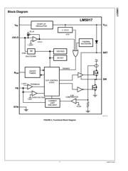
功能描述在P1P8
技术参数、封装参数在P3P4P11
应用领域在P1P17
电气规格在P3P4P5
导航目录
LM5017MR数据手册
Page:
of 17 Go
若手册格式错乱,请下载阅览PDF原文件
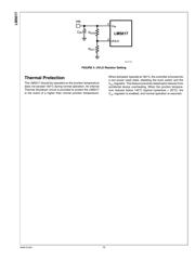
Application Information
SELECTION OF EXTERNAL COMPONENTS
Selection of external components is illustrated through a de-
sign example. The design example specifications are as fol-
lows:
Buck Converter Design Specifications
Input voltage range 12.5 V to 95 V
Output voltage 10 V
Maximum Load current 500 mA
Switching Frequency 200 kHz
RFB1, RFB2:
V
OUT
= V
FB
x (R
FB2
/R
FB1
+ 1), and since V
FB
= 1.225V, the
ratio of R
FB2
to R
FB1
calculates as 7:1. Standard values of
6.98kΩ and 1.00kΩ are chosen. Other values could be used
as long as the 7:1 ratio is maintained.
Frequency Selection:
At the minimum input voltage, the maximum switching fre-
quency of LM5017 is restricted by the forced minimum off-
time (T
OFF(MIN)
) as given by:
Similarly, at maximum input voltage, the maximum switching
frequency of LM5017 is restricted by the minimum T
ON
as
given by:
Resistor R
ON
sets the nominal switching frequency based on
the following equations:
where K = 1 x 10
–10
. Operation at high switching frequency
results in lower efficiency while providing the smallest solu-
tion. For this example a conservative 200 kHz was selected,
resulting in R
ON
= 504 kΩ. Selecting a standard value for
R
ON
= 499 kΩ results in a nominal frequency of 202 kΩ.
Inductor Selection:
The minimum inductance is selected to limit the output ripple
to 20 to 40 percent of the maximum load current. In addition,
the peak inductor current at maximum load should be smaller
than the minimum current limit as given in electrical charac-
teristics table. The inductor current ripple is given by:
The maximum ripple is observed at maximum input voltage.
Substituting V
IN
= 95 V and Δ
IL
= 40 percent x I
OUT (max)
results
in L1 = 198.4 μH. The next higher standard value of 220 μH
is chosen. The peak-to-peak minimum and maximum induc-
tor current ripples of 35 mA and 204 mA are given at minimum
and maximum input voltages respectively. The peak inductor
and switch current is given by
which is smaller than the minimum current limit. The inductor
should be able to withstand the maximum current limit of 1.3
A, which can be reached during startup and overload condi-
tions.
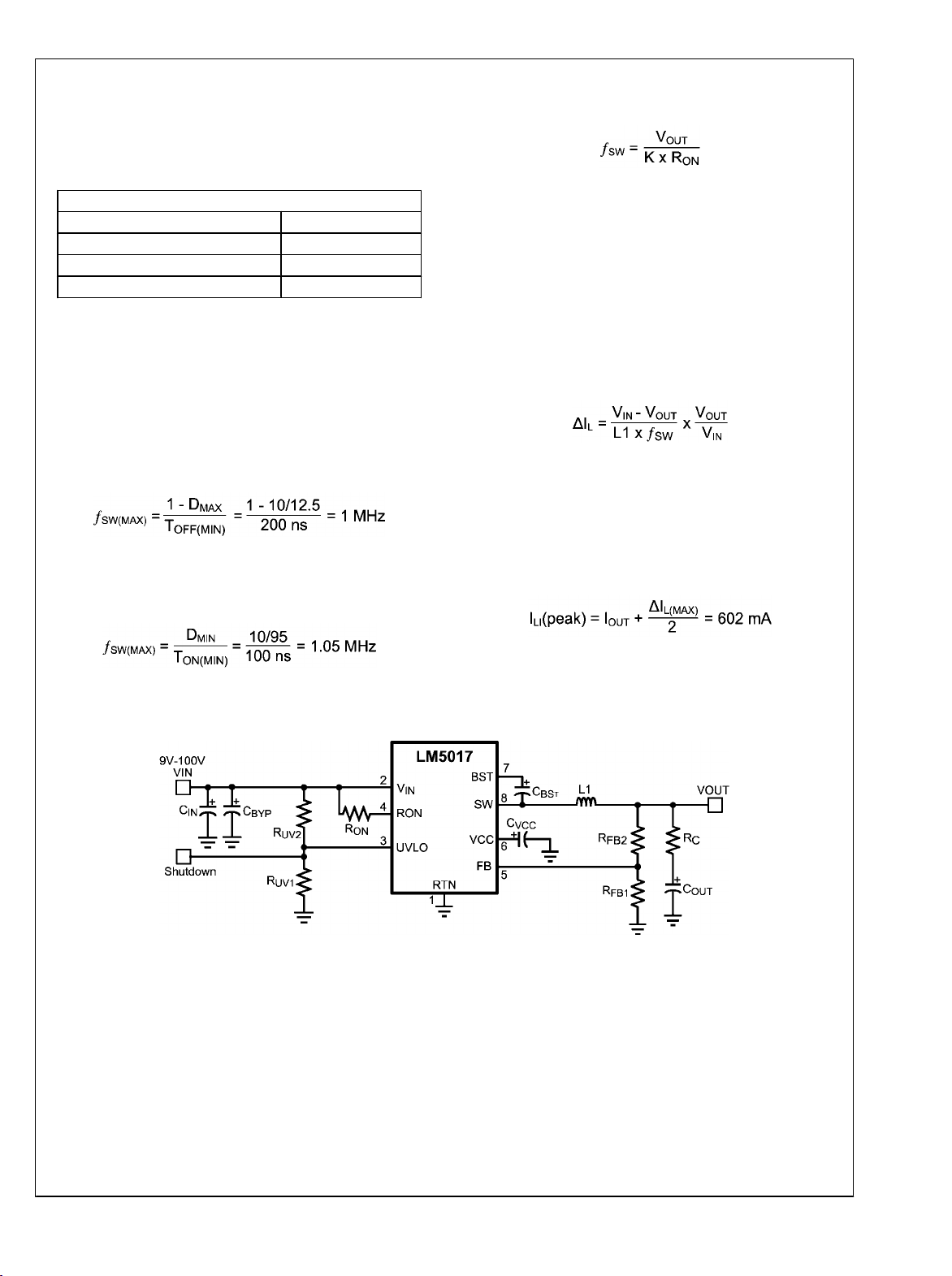
30177722
FIGURE 5. Reference Schematic for Selection of External Components
11 www.ti.com
LM5017
器件 Datasheet 文档搜索
AiEMA 数据库涵盖高达 72,405,303 个元件的数据手册,每天更新 5,000 多个 PDF 文件
