Datasheet 搜索 > 比较器 > TI(德州仪器) > LP339DR 数据手册 > LP339DR 数据手册 4/14 页
 器件3D模型
¥ 4.906
LP339DR 数据手册 - TI(德州仪器)
制造商:
TI(德州仪器)
分类:
比较器
封装:
SOIC-14
描述:
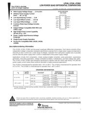
TEXAS INSTRUMENTS LP339DR 模拟比较器, 四路, 差分, 4, 8 µs, 3V 至 30V, SOIC, 14 引脚
Pictures:
3D模型
符号图
焊盘图
引脚图
产品图
页面导航:

导航目录
LP339DR数据手册
Page:
of 14 Go
若手册格式错乱,请下载阅览PDF原文件
The LP239 is obsolete
a
nd is no longer supplied.
SLCS004B − OCTOBER 1987 − REVISED SEPTEMBER 2004
4
POST OFFICE BOX 655303 • DALLAS, TEXAS 75265
APPLICATION INFORMATION
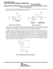
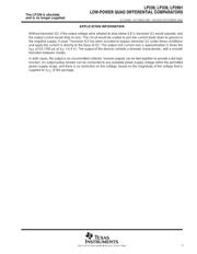
Figure 1 shows the basic configuration for using the LP239, LP339, or LP2901 comparator. Figure 2 shows the
diagram for using one of these comparators as a CMOS driver.
Figure 1. Basic Comparator
IN +
IN −
OUT
30 kΩ
+
−
V
CC
1/4 LP239, LP339,
or LP2901
Figure 2. CMOS Driver
IN +
IN −
100 kΩ
1/4 LP239, LP339,
or LP2901
1/4 SN54/74LS00 or
1/4 SN54/74ALS1000A
V
CC
+
−
12
3
OUT
All pins of any unused comparators should be grounded. The bias network of the LP239, LP339, and LP2901
establishes a drain current that is independent of the magnitude of the power-supply voltage over the range of
2 V to 30 V. It usually is necessary to use a bypass capacitor across the power supply line.
The differential input voltage may be larger than V
CC
without damaging the device. Protection should be
provided to prevent the input voltages from going negative by more than −0.3 V. The output section has two
distinct modes of operation: a Darlington mode and ground-emitter mode. This unique drive circuit permits the
device to sink 30 mA at V
O
= 2 V in the Darlington mode and 700 µA at V
O
= 0.4 V in the ground-emitter mode.
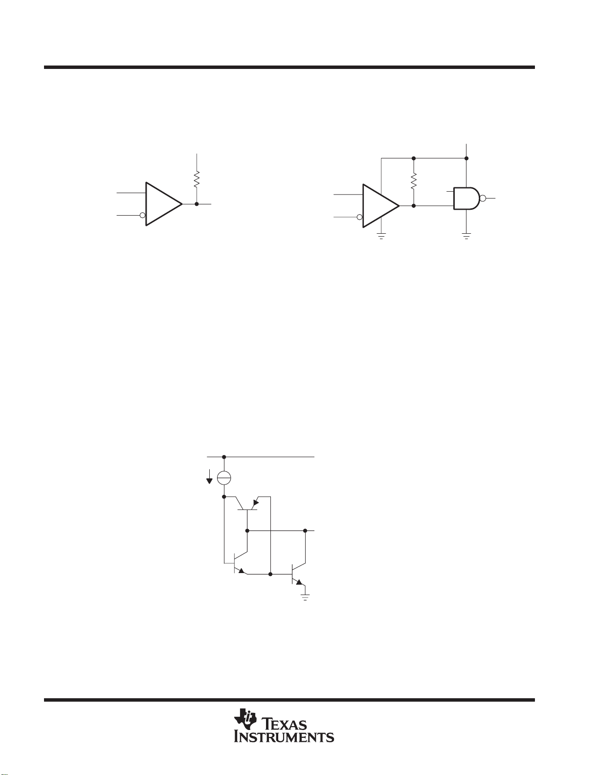
Figure 3 is a simplified schematic diagram of the output section. The output section is configured in a Darlington
connection (ignoring Q3). If the output voltage is held high enough (above 1 V), Q1 is not saturated and the
output current is limited only by the product of the h
FE
of Q1, the h
FE
of Q2, and I1 and the 60-Ω saturation
resistance of Q2. The devices are capable of driving LEDs, relays, etc. in this mode while maintaining an
ultra-low power-supply current of 60 µA, typically.
V
CC
V
O
Q2
Q1
Q3
I1 = 6 µA
Figure 3. Output-Section Schematic Diagram
器件 Datasheet 文档搜索
AiEMA 数据库涵盖高达 72,405,303 个元件的数据手册,每天更新 5,000 多个 PDF 文件
