Datasheet 搜索 > ADI(亚德诺) > LTC1624IS8#PBF 数据手册 > LTC1624IS8#PBF 数据手册 20/28 页
 器件3D模型
¥ 0.591
LTC1624IS8#PBF 数据手册 - ADI(亚德诺)
制造商:
ADI(亚德诺)
封装:
SOP
描述:
升降压型 3.5V~36V 200kHz
Pictures:
3D模型
符号图
焊盘图
引脚图
产品图
页面导航:
引脚图在P4P5Hot
典型应用电路图在P1P5P13P21P22P23P24P25P26P27P28
应用领域在P1P5P7P8P9P10P11P12P13P14P15P16
电气规格在P3P4P9P11
导航目录
LTC1624IS8#PBF数据手册
Page:
of 28 Go
若手册格式错乱,请下载阅览PDF原文件

20
LTC1624
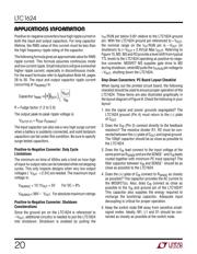
Positive-to-negative converters have high ripple current in
both the input and output capacitors. For long capacitor
lifetime, the RMS value of this current must be less than
the high frequency ripple rating of the capacitor.
The following formula gives an approximate value for RMS
ripple current. This formula assumes continuous mode
and low current ripple. Small inductors will give somewhat
higher ripple current, especially in discontinuous mode.
For the exact formulas refer to Application Note 44, pages
28 to 30. The input and output capacitor ripple current
(occurring at V
IN(MIN)
) is:
Capacitor ff I
V
V
OUT
OUT
IN
I
RMS
=
()( )
ff = Fudge factor (1.2 to 2.0)
The output peak-to-peak ripple voltage is:
V
OUT(P-P)
= R
ESR
(I
D(MAX)
)
The input capacitor can also see a very high surge current
when a battery is suddenly connected, and solid tantalum
capacitors can fail under this condition. Be sure to specify
surge tested capacitors.
Positive-to-Negative Converter: Duty Cycle
Limitations
The minimum on-time of 450ns sets a limit on how high
of input-to-output ratio can be tolerated while not skipping
cycles. This only impacts designs when very low output
voltages (V
OUT
< 2.5V) are needed. The maximum input
voltage is:
V
IN(MAX)
< 10.1V
OUT
+ 5V For DC > 9%
V
IN(MAX)
< 36V – V
OUT
For absolute maximum ratings
Positive-to-Negative Converter: Shutdown
Considerations
Since the ground pin on the LTC1624 is referenced to
–V
OUT
, additional circuitry is needed to put the LTC1624
into shutdown. Shutdown is enabled by pulling the
I
TH
/RUN pin below 0.8V relative to the LTC1624 ground
pin. With the LTC1624 ground pin referenced to –V
OUT
,
the nonimal range on the I
TH
/RUN pin is –V
OUT
(in
shutdown) to (–V
OUT
+ 2.4V)(at Max I
OUT
). Referring to
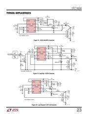
Figure 15, M2, M3 and R3 provide a level shift from typical
TTL levels to the LTC1624 operating as positive-to-nega-
tive converter. MOSFET M3 supplies gate drive to M2
during shutdown, while M2 pulls the I
TH/RUN
pin voltage to
–V
OUT
, shutting down the LTC1624.
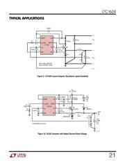
Step-Down Converters: PC Board Layout Checklist
When laying out the printed circuit board, the following
checklist should be used to ensure proper operation of the
LTC1624. These items are also illustrated graphically in
the layout diagram of Figure 9. Check the following in your
layout:
1. Are the signal and power grounds segregated? The
LTC1624 ground (Pin 4) must return to the (–) plate
of C
OUT.
2. Does the V
FB
(Pin 3) connect directly to the feedback
resistors? The resistive divider R1, R2 must be con-
nected between the (+) plate of C
OUT
and signal ground.
The 100pF capacitor should be as close as possible to
the LTC1624.
3. Does the V
IN
lead connect to the input voltage at the
same point as R
SENSE
and are the SENSE
–
and V
IN
leads
routed together with minimum PC trace spacing? The
filter capacitor between V
IN
and SENSE
–
should be as
close as possible to the LTC1624.
4. Does the (+) plate of C
IN
connect to R
SENSE
as closely
as possible? This capacitor provides the AC current to
the MOSFET(s). Also, does C
IN
connect as close as
possible to the V
IN
and ground pin of the LTC1624?
This capacitor also supplies the energy required to
recharge the bootstrap capacitor. Adequate input
decoupling is critical for proper operation.
5. Keep the switch node SW away from sensitive small-
signal nodes. Ideally, M1, L1 and D1 should be con-
nected as closely as possible at the switch node.
APPLICATIONS INFORMATION
WUU
U
器件 Datasheet 文档搜索
AiEMA 数据库涵盖高达 72,405,303 个元件的数据手册,每天更新 5,000 多个 PDF 文件
