Datasheet 搜索 > ADI(亚德诺) > LTC3736EGN-1#PBF 数据手册 > LTC3736EGN-1#PBF 数据手册 20/28 页
 器件3D模型
¥ 24.454
LTC3736EGN-1#PBF 数据手册 - ADI(亚德诺)
制造商:
ADI(亚德诺)
封装:
SSOP
描述:
降压型 2.75V~9.8V 750kHz
Pictures:
3D模型
符号图
焊盘图
引脚图
产品图
页面导航:


导航目录
LTC3736EGN-1#PBF数据手册
Page:
of 28 Go
若手册格式错乱,请下载阅览PDF原文件

20
LTC3736-1
37361f
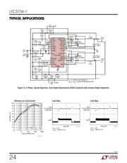
APPLICATIO S I FOR ATIO
WUUU
change as the supply is reduced down to 2.4V. Also shown
is the effect on V
REF
.
Minimum On-Time Considerations
Minimum on-time, t
ON(MIN)
,
is the smallest amount of time
in which the LTC3736-1 is capable of turning the top
P-channel MOSFET on and then off. It is determined by
internal timing delays and the gate charge required to turn
on the top MOSFET. Low duty cycle and high frequency
applications may approach the minimum on-time limit
and care should be taken to ensure that:
t
V
fV
ON MIN
OUT
OSC IN
()
•
<
If the duty cycle falls below what can be accommodated
by the minimum on-time, the LTC3736-1 will begin to skip
cycles. The output voltage will continue to be regulated,
but the ripple current and ripple voltage will increase. The
minimum on-time for the LTC3736
-1
is typically about
250ns. However, as the peak sense voltage (I
L(PEAK)
•
R
DS(ON)
) decreases, the minimum on-time gradually in-
creases up to about 300ns.
Efficiency Considerations
The efficiency of a switching regulator is equal to the
output power divided by the input power times 100%. It is
often useful to analyze individual losses to determine what
is limiting efficiency and which change would produce the
most improvement. Efficiency can be expressed as:
Efficiency = 100% – (L1 + L2 + L3 + …)
where L1, L2, etc. are the individual losses as a percentage
of input power.
Although all dissipative elements in the circuit produce
losses, five main sources usually account for most of the
losses in LTC3736-1 circuits: 1) LTC3736-1 DC bias
current, 2) MOSFET gate charge current, 3) I
2
R losses,
and 4) transition losses.
1) The V
IN
(pin) current is the DC supply current, given in
the electrical characteristics, excluding MOSFET driver
currents. V
IN
current results in a small loss that in-
creases with V
IN
.
2) MOSFET gate charge current results from switching the
gate capacitance of the power MOSFETs. Each time a
MOSFET gate is switched from low to high to low again,
a packet of charge dQ moves from SENSE
+
to ground.
The resulting dQ/dt is a current out of SENSE
+
, which is
typically much larger than the DC supply current. In
continuous mode, I
GATECHG
= f • Q
P
.
3) I
2
R losses are calculated from the DC resistances of the
MOSFETs and inductor. In continuous mode, the aver-
age output current flows through L but is “chopped”
between the top P-channel MOSFET and the bottom
N-channel MOSFET. The MOSFET R
DS(ON)
s multiplied
by duty cycle can be summed with the resistance of L
to obtain I
2
R losses.
4) Transition losses apply to the top external P-channel
MOSFET and increase with higher operating frequen-
cies and input voltages. Transition losses can be esti-
mated from:
Transition Loss = 2 (V
IN
)
2
I
O(MAX)
C
RSS
(f)
Other losses, including C
IN
and C
OUT
ESR dissipative
losses and inductor core losses, generally account for less
than 2% total additional loss.
Checking Transient Response
The regulator loop response can be checked by looking at
the load transient response. Switching regulators take
several cycles to respond to a step in load current. When
a load step occurs, V
OUT
immediately shifts by an amount
equal to (∆I
LOAD
)(ESR), where ESR is the effective series
resistance of
COUT
. ∆I
LOAD
also begins to charge or dis-
charge C
OUT
, which generates a feedback error signal. The
regulator loop then returns V
OUT
to its steady-state value.
During this recovery time, V
OUT
can be monitored for over-
shoot or ringing. OPTI-LOOP compensation allows the
transient response to be optimized over a wide range of
output capacitance and ESR values.
The I
TH
series R
C
-C
C
filter (see Functional Diagram) sets
the dominant pole-zero loop compensation. The I
TH
exter-
nal components shown in the Typical Application on the
front page of this data sheet will provide an adequate
starting point for most applications. The values can be
器件 Datasheet 文档搜索
AiEMA 数据库涵盖高达 72,405,303 个元件的数据手册,每天更新 5,000 多个 PDF 文件
