Datasheet 搜索 > 电源监控芯片 > Maxim Integrated(美信) > MAX690TESA+ 数据手册 > MAX690TESA+ 数据手册 4/13 页

 器件3D模型
¥ 62.392
MAX690TESA+ 数据手册 - Maxim Integrated(美信)
制造商:
Maxim Integrated(美信)
分类:
电源监控芯片
封装:
SOIC-8
描述:
MAXIM INTEGRATED PRODUCTS MAX690TESA+ 芯片, 微处理器监控器, 5.5V, NSOIC-8
Pictures:
3D模型
符号图
焊盘图
引脚图
产品图
页面导航:
导航目录
MAX690TESA+数据手册
Page:
of 13 Go
若手册格式错乱,请下载阅览PDF原文件
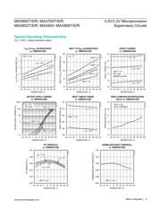
(V
CC
= 3.17V to 5.5V for the MAX690T/MAX704T/MAX80_T, V
CC
= 3.02V to 5.5V for the MAX690S/MAX704S/MAX80_S, V
CC
= 2.72V to
5.5V for the MAX690R/MAX704R/MAX80_R; VBATT = 3.6V; T
A
= T
MIN
to T
MAX
; unless otherwise noted. Typical values are at T
A
= +25C.)
Note 1: V
CC
supply current, logic input leakage, watchdog functionality (MAX690_/802_/805_/804_), MR functionality
(MAX704_/806_), PFI functionality, state of RESET (MAX690_/704_/802_/806_), and RESET (MAX804_/805_) tested at
VBATT = 3.6V, and V
CC
= 5.5V. The state of RESET or RESET and PFO is tested at V
CC
= V
CC
min.
Note 2: Tested at VBATT = 3.6V, V
CC
= 3.5V and 0V. The battery current will rise to 10µA over a narrow transition window around
V
CC
= 1.9V.
Note 3:
Leakage current into the battery is tested under the worst-case conditions at V
CC
= 5.5V, VBATT = 1.8V and at V
CC
= 1.5V,
VBATT= 1.0V.
Note 4: Guaranteed by design.
Note 5: When V
SW
> V
CC
> VBATT, V
OUT
remains connected to V
CC
until V
CC
drops below VBATT. The V
CC
-to-VBATT compara-
tor has a small 25mV typical hysteresis to prevent oscillation. For V
CC
< 1.75V (typ), V
OUT
switches to VBATT regardless
of the voltage on VBATT.
Note 6: When VBATT > V
CC
> V
SW
, V
OUT
remains connected to V
CC
until V
CC
drops below the battery switch threshold (V
SW
).
Note 7: V
OUT
switches from VBATT to V
CC
when V
CC
rises above the reset threshold, independent of VBATT. Switchover back to
V
CC
occurs at the exact voltage that causes RESET to go high (on the MAX804_/805_, RESET goes low); however
switchover occurs 200ms prior to reset.
Note 8: The reset threshold tolerance is wider for V
CC
rising than for V
CC
falling to accommodate the 10mV typical hysteresis,
which prevents internal oscillation.
Note 9: The leakage current into or out of the RESET pin is tested with RESET asserted (RESET output high impedance).
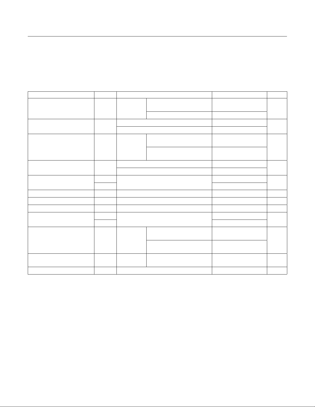
PARAMETER SYMBOL CONDITIONS MIN TYP MAX UNITS
PFI Input Threshold V
PFT
V
CC
< 3.6V
V
PFI
falling
MAX802_C/E, MAX804_C/E,
MAX806_C/E
1.212 1.237 1.262
V
MAX690_/MAX704_/MAX805_ 1.187 1.237 1.287
PFI Input Current
MAX690_C/E, MAX704_C/E, MAX80_ _C/E -25 2 25
nA
MAX690_M, MAX704_M, MAX80_ _M -500 2 500
PFI Hysteresis, PFI Rising V
PFH
V
CC
< 3.6V
MAX690_C/E, MAX704_C/E,
MAX80_ _C/E
10 20
mV
MAX690_M, MAX704_M,
MAX80_ _M
10 25
PFI Input Current
MAX690_C/E, MAX704_C/E, MAX80_ _C/E -25 2 25
nA
MAX690_M, MAX704_M, MAX80_ _M -500 2 500
MR Input Threshold
V
IH
MAX704_/MAX806_ only
0.7 x V
CC
V
V
IL
0.3 x V
CC
MR Pulse Width
t
MR
MAX704_/MAX806_ only 100 20 ns
MR to Reset Delay
t
MD
MAX704_/MAX806_ only 60 500 ns
MR Pull-Up Current MAX704_/MAX806_ only, MR = 0V, V
CC
= 3V
20 60 350 µA
WDI Input Threshold
V
IH
MAX690_/MAX802_/MAX804_/MAX805_ only
0.7 x V
CC
V
V
IL
0.3 x V
CC
WDI Input Current
0V< V
CC
<
5.5V
MAX690_C/E, MAX802_C/E,
MAX804_C/E, MAX805_C/E
-1 +0.01 +1
µA
MAX690_M, MAX802_M,
MAX804_M, MAX805_M
-10 +0.01 +10
Watchdog Timeout Period t
WD
V
CC
< 3.6V
MAX690/MAX802/MAX804/
MAX805 only
1.12 1.60 2.24 s
WDI Pulse Width MAX690_/MAX802_/MAX804_/MAX805_ only 100 20 ns
MAX690T/S/R, MAX704T/S/R,
MAX802T/S/R, MAX804−MAX806T/S/R
3.0V/3.3V Microprocessor
Supervisory Circuits
www.maximintegrated.com
Maxim Integrated
│
4
Electrical Characteristics (continued)
器件 Datasheet 文档搜索
AiEMA 数据库涵盖高达 72,405,303 个元件的数据手册,每天更新 5,000 多个 PDF 文件
