Datasheet 搜索 > Motorola(摩托罗拉) > MBR0530T3 数据手册 > MBR0530T3 数据手册 1/4 页


¥ 0
MBR0530T3 数据手册 - Motorola(摩托罗拉)
制造商:
Motorola(摩托罗拉)
Pictures:
3D模型
符号图
焊盘图
引脚图
产品图
页面导航:
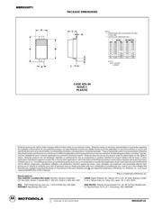
封装尺寸在P4
标记信息在P1
技术参数、封装参数在P1
电气规格在P1
导航目录
MBR0530T3数据手册
Page:
of 4 Go
若手册格式错乱,请下载阅览PDF原文件
1
Rectifier Device Data
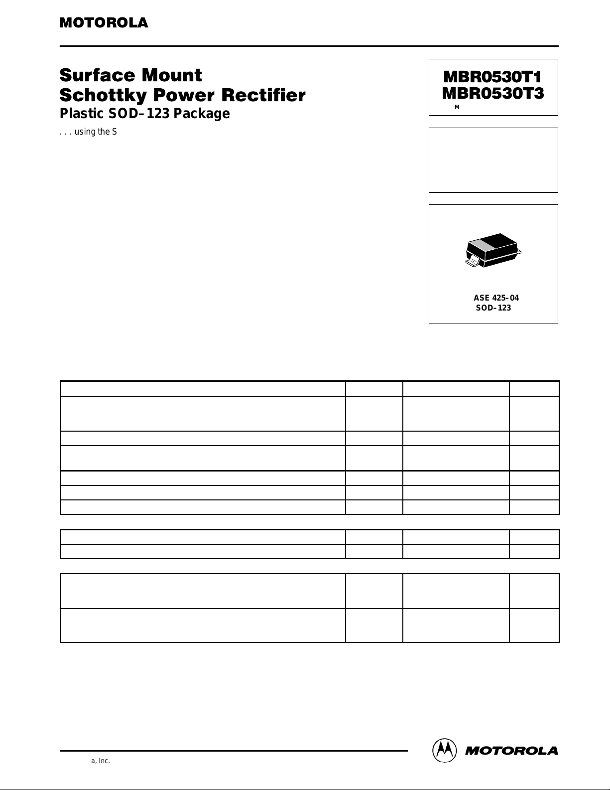
Plastic SOD–123 Package
. . . using the Schottky Barrier principle with a large area metal–to–silicon power
diode. Ideally suited for low voltage, high frequency rectification or as free
wheeling and polarity protection diodes in surface mount applications where
compact size and weight are critical to the system. This package also provides
an easy to work with alternative to leadless 34 package style. These
state–of–the–art devices have the following features:
• Guardring for Stress Protection
• Low Forward Voltage
• 125°C Operating Junction Temperature
• Epoxy Meets UL94, VO at 1/8″
• Package Designed for Optimal Automated Board Assembly
Mechanical Characteristics
• Reel Options: MBR0530T1 = 3,000 per 7″ reel/8 mm tape
Reel Options: MBR0530T3 = 10,000 per 13″ reel/8 mm tape
• Device Marking: B3
• Polarity Designator: Cathode Band
• Weight: 11.7 mg (approximately)
• Case: Epoxy, Molded
• Finish: All External Surfaces Corrosion Resistant and Terminal Leads are Readily Solderable
• Lead and Mounting Surface Temperature for Soldering Purposes: 260°C Max. for 10 Seconds
MAXIMUM RATINGS
Rating Symbol Value Unit
Peak Repetitive Reverse Voltage
Working Peak Reverse Voltage
DC Blocking Voltage
V
RRM
V
RWM
V
R
30 Volts
Average Rectified Forward Current (Rated V
R
) T
L
= 100°C I
F(AV)
0.5 Amps
Non–repetitive Peak Surge Current
(Surge applied at rated load conditions halfwave, single phase, 60 Hz)
I
FSM
5.5 Amps
Storage Temperature T
stg
–65 to +125 °C
Operating Junction Temperature T
J
–65 to +125 °C
Voltage Rate of Change (Rated V
R
) dv/dt 1000 V/µs
THERMAL CHARACTERISTICS
Thermal Resistance — Junction to Ambient (1) R
θJA
340 °C/W
Thermal Resistance — Junction to Lead (1) R
θJL
150 °C/W
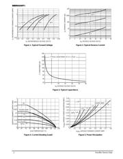
ELECTRICAL CHARACTERISTICS
Maximum Instantaneous Forward Voltage (2)
(i
F
= 0.1 Amps, T
J
= 25°C)
(i
F
= 0.5 Amps, T
J
= 25°C)
V
F
0.375
0.43
Volts
Maximum Instantaneous Reverse Current (2)
(Rated dc Voltage, T
C
= 25°C)
(V
R
= 15 V, T
C
= 25°C)
I
R
130
20
µA
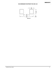
(1) FR–4 or FR–5 = 3.5 x 1.5 inches using the Motorola minimum recommended footprint.
(2) Pulse Test: Pulse Width = 300 µs, Duty Cycle ≤ 2%.
Preferred devices are Motorola recommended choices for future use and best overall value.
Order this document
by MBR0530T1/D
SEMICONDUCTOR TECHNICAL DATA
Motorola, Inc. 1996
Rev 1
SCHOTTKY BARRIER
RECTIFIER
0.5 AMPERES
30 VOLTS
CASE 425–04
SOD–123
Motorola Preferred Devices
器件 Datasheet 文档搜索
AiEMA 数据库涵盖高达 72,405,303 个元件的数据手册,每天更新 5,000 多个 PDF 文件
