Datasheet 搜索 > 8位微控制器 > NXP(恩智浦) > MC9S08QD4CSC 数据手册 > MC9S08QD4CSC 数据手册 3/8 页
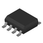
 器件3D模型
¥ 12.098
MC9S08QD4CSC 数据手册 - NXP(恩智浦)
制造商:
NXP(恩智浦)
分类:
8位微控制器
封装:
SOIC-8
描述:
NXP MC9S08QD4CSC 微控制器, 8位, QD系列, S08QD, 16 MHz, 4 KB, 256 Byte, 8 引脚, SOIC
Pictures:
3D模型
符号图
焊盘图
引脚图
产品图
页面导航:
功能描述在P1P2P4P5P6P7P8
导航目录
MC9S08QD4CSC数据手册
Page:
of 8 Go
若手册格式错乱,请下载阅览PDF原文件

Mask Set Errata for 9S08QD4, Mask 0M15D
Freescale Semiconductor
3
• Use the ICS in any of the modes with the FLL disabled. This includes: FLL bypassed internal (FBI),
FLL bypassed internal low power (FBILP), FLL bypassed external (FBI), FLL bypassed external
low power (FBELP) modes. (Not all devices have EXTAL and XTAL pins available to run the device
with an external reference.)
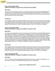
PWM Boundary Case Issues in HCS08 Timer PWM Module (TPM) SE110-TPM
This errata describes boundary case issues that primarily affect the center-aligned PWM mode of
operation. While investigating these issues, additional, less significant, issues were discovered. These
will be explained, although they should not cause any significant problems in normal applications.
In center-aligned PWM mode, the timer counter counts up until it reaches the modulo value in
TPMMODH:TPMMODL, reverses direction, and then counts down until it reaches zero, where it reverses
and counts up again. A period of the PWM output is centered around the leading edge of the zero count
and the period is considered to start when the count changes from TPMMODH:TPMMODL–1 to
TPMMODH:TPMMODL (the same point where the counter changes from up-counting to down-counting).
The zero value and the maximum modulo value occur for only one timer count cycle each, while all other
values occur twice (once during the down-counting phase and again during the up-counting phase).
Therefore, the total period of the PWM signal is two times the value in TPMMODH:TPMMODL.
The value on each TPM timer output pin is controlled by an internal flip-flop that is cleared at reset but is
not readable by software. These internal flip-flops change state when timer output compare events or
PWM duty cycle compare events occur (when the channel value registers match the timer count
registers). This leads to these outputs remaining in a previous state until a compare event occurs after
changing the configuration of the timer system. When the timer is initialized the first time after a reset, the
state of these output flip-flops is known to be reset (logic low). If the configuration is changed after the
channel has been running in another configuration for some period of time, you sometimes do not know
the state of these internal flip-flops (and therefore the state of the timer output pins) until a new channel
value register compare event occurs. There is nothing improper about these periods before the first event
occurs, however some users might be surprised the first time they notice this behavior.
When the MCU is reset, the count (TPMCNTH:TPMCNTL) is reset to 0x0000. If the timer is configured
for center-aligned pulse-width modulation (PWM) and then the clock is started, this corresponds to the
middle of a PWM period. If the internal flip-flop corresponding to the output was at the inactive level when
the PWM started, this would appear as if there was an extra half period of delay before the first full PWM
cycle started. If the internal flip-flop corresponding to the output happened to be at the active level when
this PWM was started, a pulse equivalent to half of a normal duty cycle pulse could be produced at the
PWM output pin.
There are eight cases discussed in this errata:
• Cases 1 and 2 — These are two error cases near the 100% duty cycle boundary. The first is when
the channel value registers are set equal to the modulo value. The second is when the channel
value registers are set to one less than the modulo value.
• Cases 3, 4, and 5 — These cases are related to changing the channel value to or from 0x0000.
The errors depend upon whether this is done during the first or second half of the center-aligned
PWM period. In all of these cases, the workaround strategy is to produce 0% duty cycle with a
negative channel value instead of using the 0x0000 value. This can be done by checking any value
器件 Datasheet 文档搜索
AiEMA 数据库涵盖高达 72,405,303 个元件的数据手册,每天更新 5,000 多个 PDF 文件
