Datasheet 搜索 > DC/DC转换器 > Microchip(微芯) > MCP1640D-I/MC 数据手册 > MCP1640D-I/MC 数据手册 12/32 页

 器件3D模型
¥ 4.7
MCP1640D-I/MC 数据手册 - Microchip(微芯)
制造商:
Microchip(微芯)
分类:
DC/DC转换器
封装:
DFN-8
描述:
MICROCHIP MCP1640D-I/MC. 芯片, 同步升压稳压器, DFN-8
Pictures:
3D模型
符号图
焊盘图
引脚图
产品图
页面导航:
引脚图在P9Hot
典型应用电路图在P2P15P19
原理图在P12
标记信息在P21
封装信息在P21P22P23P25P29
功能描述在P1P12
技术参数、封装参数在P4
应用领域在P1P15
电气规格在P4
型号编号列表在P11


导航目录
MCP1640D-I/MC数据手册
Page:
of 32 Go
若手册格式错乱,请下载阅览PDF原文件
MCP1640/B/C/D
DS20002234D-page 12 2010-2015 Microchip Technology Inc.
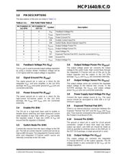
4.2 Functional Description
The MCP1640/B/C/D is a compact, high-efficiency,
fixed frequency, step-up DC-DC converter that
provides an easy-to-use power supply solution for
applications powered by either single-cell, two-cell, or
three-cell alkaline, NiCd, NiMH, and single-cell Li-Ion or
Li-Polymer batteries.
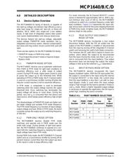
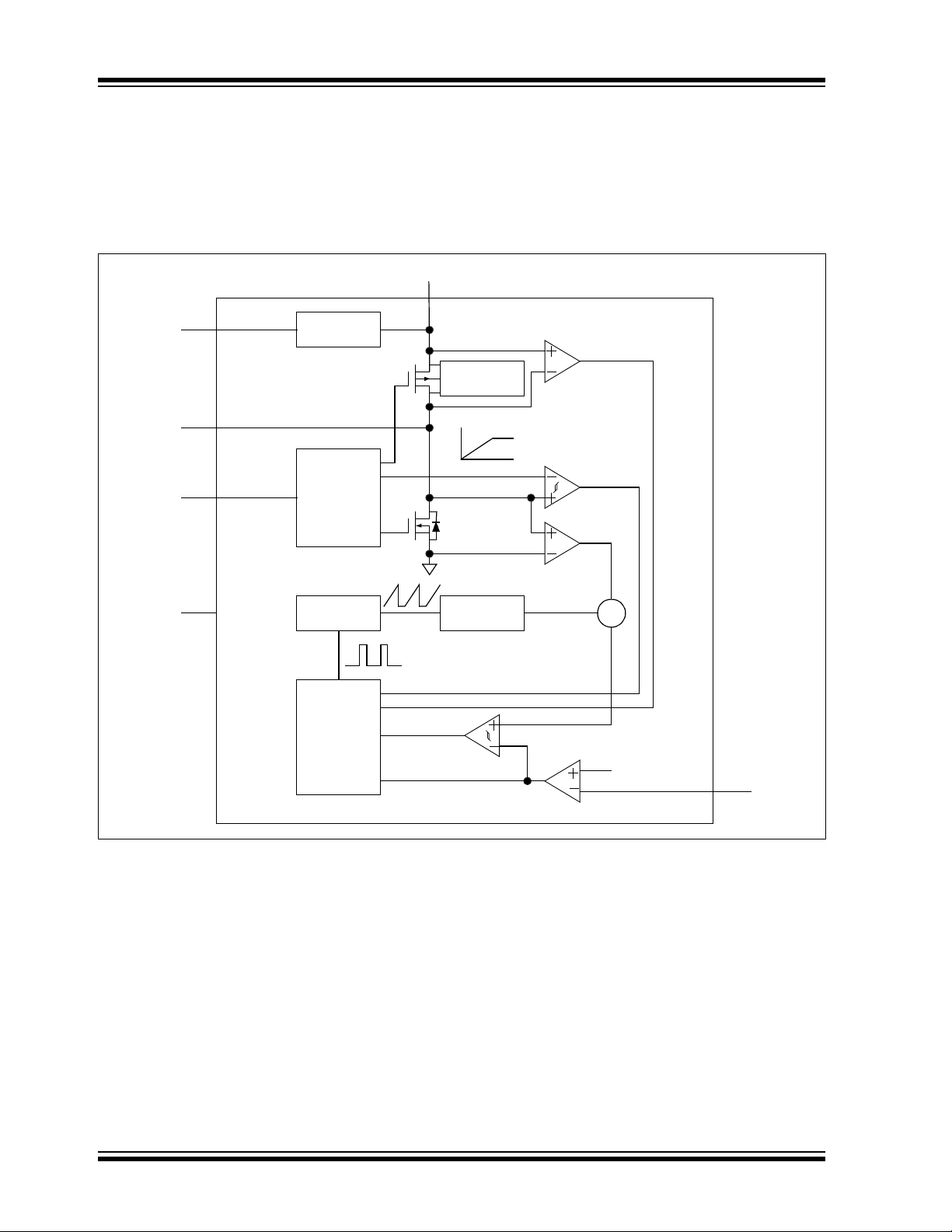
Figure 4-1 depicts the functional block diagram of the
MCP1640/B/C/D.
FIGURE 4-1: MCP1640/B/C/D Block Diagram.
4.2.1 LOW-VOLTAGE START-UP
The MCP1640/B/C/D is capable of starting from a low
input voltage. Start-up voltage is typically 0.65V for a
3.3V output and 1 mA resistive load.
When enabled, the internal start-up logic turns the
rectifying P-Channel switch on until the output
capacitor is charged to a value close to the input
voltage. The rectifying switch is current-limited to
approximately 100 mA during this time. This will affect
the start-up under higher load currents, and the device
may not start to the nominal value. After charging the
output capacitor to the input voltage, the device starts
switching. If the input voltage is below 1.6V, the device
runs open-loop with a fixed duty cycle of 70% until the
output reaches 1.6V. During this time, the boost switch
current is limited to 50% of its nominal value. Once the
output voltage reaches 1.6V, normal closed-loop PWM
operation is initiated.
The MCP1640/B/C/D charges an internal capacitor
with a very weak current source. The voltage on this
capacitor, in turn, slowly ramps the current limit of the
boost switch to its nominal value. The soft-start
capacitor is completely discharged in the event of a
commanded shutdown or a thermal shutdown.
There is no undervoltage lockout feature for the
MCP1640/B/C/D. The device will start-up at the lowest
possible voltage and run down to the lowest possible
voltage. For typical battery applications, this may result
in “motor-boating” (emitting a low-frequency tone) for
deeply discharged batteries.
Gate Drive
and
Shutdown
Control
Logic
V
IN
EN
V
OUT
GND
I
SENSE
I
ZERO
I
LIMIT
.3V
0V
Soft Start
Direction
Control
Oscillator
Slope
Comp.
S
PWM/PFM
Logic
1.21V
Internal
Bias
SW
FB
EA
器件 Datasheet 文档搜索
AiEMA 数据库涵盖高达 72,405,303 个元件的数据手册,每天更新 5,000 多个 PDF 文件
