Datasheet 搜索 > SCR晶闸管 > Littelfuse(力特) > MCR12DSMT4G 数据手册 > MCR12DSMT4G 数据手册 1/7 页


¥ 3.596
MCR12DSMT4G 数据手册 - Littelfuse(力特)
制造商:
Littelfuse(力特)
分类:
SCR晶闸管
封装:
TO-252-3
描述:
相位控制闸流晶体管,ON Semiconductor### 闸流晶体管 - ON Semiconductor闸流晶体管是一种固态半导体设备,具有四层交替的 N 型和 P 型材料。 它们充当双稳态开关,当它们的栅极接收到电流触发时发挥作用,并在处于正向偏压时继续发挥作用。 闸流晶体管与硅控整流器 (SCR) 同义。
Pictures:
3D模型
符号图
焊盘图
引脚图
产品图
页面导航:


导航目录
MCR12DSMT4G数据手册
Page:
of 7 Go
若手册格式错乱,请下载阅览PDF原文件
© Semiconductor Components Industries, LLC, 2013
June, 2013 − Rev. 7
1 Publication Order Number:
MCR12DSM/D
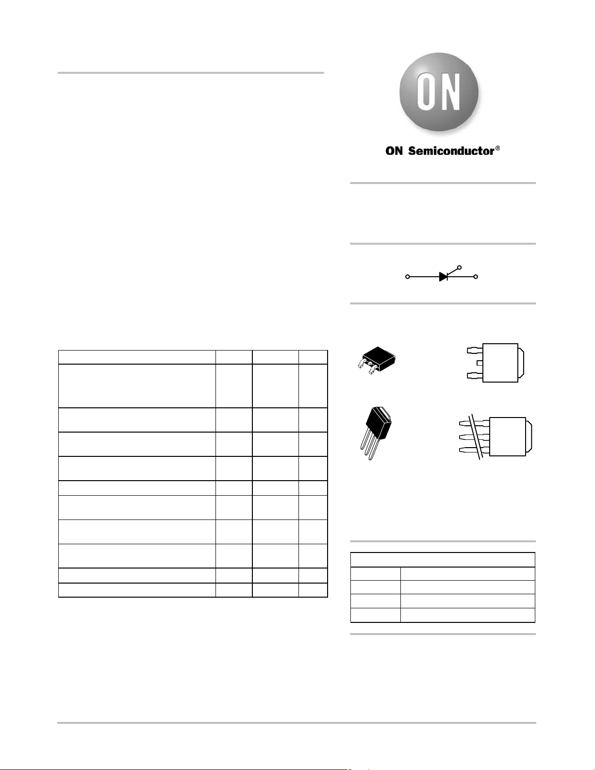
MCR12DSM, MCR12DSN
Sensitive Gate Silicon
Controlled Rectifiers
Reverse Blocking Thyristors
Designed for high volume, low cost, industrial and consumer
applications such as motor control; process control; temperature, light
and speed control; CDI (Capacitive Discharge Ignition); and small
engines.
Features
• Small Size
• Passivated Die for Reliability and Uniformity
• Low Level Triggering and Holding Characteristics
• Epoxy Meets UL 94 V−0 @ 0.125 in
• ESD Ratings: Human Body Model, 3B u 8000 V
Machine Model, C u 400 V
• These are Pb−Free Devices
MAXIMUM RATINGS (T
J
= 25°C unless otherwise noted)
Rating Symbol Value Unit
Peak Repetitive Off−State Voltage (Note 1)
(T
J
= −40 to 110°C, Sine Wave, 50 Hz to
60 Hz) MCR12DSM
MCR12DSN
V
DRM,
V
RRM
600
800
V
On−State RMS Current
(180° Conduction Angles; T
C
= 75°C)
I
T(RMS)
12 A
Average On−State Current
(180° Conduction Angles; T
C
= 75°C)
I
T(AV)
7.6 A
Peak Non-Repetitive Surge Current
(1/2 Cycle, Sine Wave 60 Hz, T
J
= 110°C)
I
TSM
100 A
Circuit Fusing Consideration (t = 8.3 msec) I
2
t 41 A
2
sec
Forward Peak Gate Power
(Pulse Width ≤ 10 sec, T
C
= 75°C)
P
GM
5.0 W
Forward Average Gate Power
(t = 8.3 msec, T
C
= 75°C)
P
G(AV)
0.5 W
Forward Peak Gate Current
(Pulse Width ≤ 10 sec, T
C
= 75°C)
I
GM
2.0 A
Operating Junction Temperature Range T
J
−40 to 110 °C
Storage Temperature Range T
stg
−40 to 150 °C
Stresses exceeding Maximum Ratings may damage the device. Maximum
Ratings are stress ratings only. Functional operation above the Recommended
Operating Conditions is not implied. Extended exposure to stresses above the
Recommended Operating Conditions may affect device reliability.
1. V
DRM
and V
RRM
for all types can be applied on a continuous basis. Ratings
apply for zero or negative gate voltage; however, positive gate voltage shall
not be applied concurrent with negative potential on the anode. Blocking
voltages shall not be tested with a constant current source such that the
voltage ratings of the device are exceeded.
SCRs
12 AMPERES RMS
600 − 800 VOLTS
K
G
A
PIN ASSIGNMENT
1
2
3
Anode
Gate
Cathode
4
Anode
See detailed ordering and shipping information in the package
dimensions section on page 5 of this data sheet.
ORDERING INFORMATION
http://onsemi.com
IPAK
CASE 369D
STYLE 4
DPAK
CASE 369C
STYLE 4
MARKING
DIAGRAMS
Y = Year
WW = Work Week
R12DSx = Device Code
x= M or N
G=Pb−Free Package
1
2
3
4
YWW
R1
2DSxG
1
2
3
4
YWW
R1
2DSxG
器件 Datasheet 文档搜索
AiEMA 数据库涵盖高达 72,405,303 个元件的数据手册,每天更新 5,000 多个 PDF 文件
