Datasheet 搜索 > DC/DC转换器 > Micrel(迈瑞) > MIC24051YJL TR 数据手册 > MIC24051YJL TR 数据手册 14/30 页

¥ 9.716
MIC24051YJL TR 数据手册 - Micrel(迈瑞)
制造商:
Micrel(迈瑞)
分类:
DC/DC转换器
封装:
QFN-28
描述:
MICREL SEMICONDUCTOR MIC24051YJL TR 直流-直流开关降压(逐步递减)稳压器, 可调, 4.5V-19V输入, 800mV-5.5V输出, 6A输出, QFN-28
Pictures:
3D模型
符号图
焊盘图
引脚图
产品图
页面导航:
导航目录
MIC24051YJL TR数据手册
Page:
of 30 Go
若手册格式错乱,请下载阅览PDF原文件

Micrel, Inc.
MIC24051
November
2012 14
M9999-112612-A
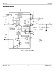
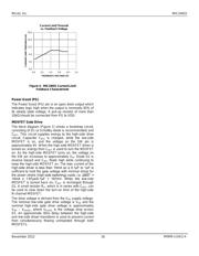
Functional Description
The MIC24051 is an adaptive ON-time synchronous
step-down DC/DC regulator with an internal 5V linear
regulator and a Power Good (PG) output. It is designed
to operate over a wide input voltage range from 4.5V to
19V and provides a regulated output voltage at up to 6A
of output current. An adaptive ON-time control scheme is
employed in to obtain a constant switching frequency
and to simplify the control compensation. Overcurrent
protection is implemented without the use of an external
sense resistor. The device includes an internal soft-start
function which reduces the power supply input surge
current at start-up by controlling the output voltage rise
time.
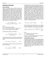
Theory of Operation
The MIC24051 operates in a continuous mode as shown
in Figure 1.
Continuous Mode
In continuous mode, the output voltage is sensed by the
MIC24051 feedback pin FB via the voltage divider R1
and R2, and compared to a 0.8V reference voltage V
REF
at the error comparator through a low gain
transconductance (g
m
) amplifier. If the feedback voltage
decreases and the output of the g
m
amplifier is below
0.8V, then the error comparator will trigger the control
logic and generate an ON-time period. The ON-time
period length is predetermined by the “FIXED t
ON
ESTIMATION” circuitry:
kHz600V
V
t
IN
OUT
)ESTIMATED(ON
×
=
Eq. 1
where V
OUT
is the output voltage and V
IN
is the power
stage input voltage.
At the end of the ON-time period, the internal high-side
driver turns off the high-side MOSFET and the low-side
driver turns on the low-side MOSFET. The OFF-time
period length depends upon the feedback voltage in
most cases. When the feedback voltage decreases and
the output of the g
m
amplifier is below 0.8V, the ON-time
period is triggered and the OFF-time period ends. If the
OFF-time period determined by the feedback voltage is
less than the minimum OFF-time t
OFF(min)
, which is about
300ns, the MIC24051 control logic will apply the t
OFF(min)
instead. t
OFF(min)
is required to maintain enough energy in
the boost capacitor (C
BST
) to drive the high-side
MOSFET.
The maximum duty cycle is obtained from the 300ns
t
OFF(min)
:
SS
)MIN(OFFS
MAX
t
ns300
1
t
tt
D −=
−
=
Eq. 2
where t
S
= 1/600kHz = 1.66μs.
It is not recommended to use MIC24051 with a OFF-time
close to t
OFF(min)
during steady-state operation. Also, as
V
OUT
increases, the internal ripple injection will increase
and reduce the line regulation performance. Therefore,
the maximum output voltage of the MIC24051 should be
limited to 5.5V and the maximum external ripple injection
should be limited to 200mV. Please refer to “Setting
Output Voltage” subsection in Application Information for
more details.
The actual ON-time and resulting switching frequency
will vary with the part-to-part variation in the rise and fall
times of the internal MOSFETs, the output load current,
and variations in the VDD voltage. Also, the minimum t
ON
results in a lower switching frequency in high V
IN
to V
OUT
applications, such as 18V to 1.0V. The minimum t
ON
measured on the MIC24051 evaluation board is about
100ns. During load transients, the switching frequency is
changed due to the varying OFF-time.
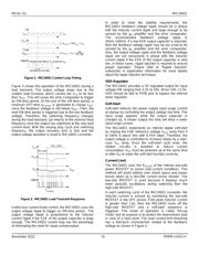
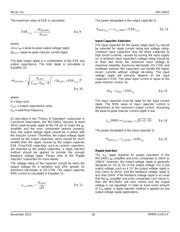
To illustrate the control loop operation, we will analyze
both the steady-state and load transient scenarios.
Figure 2 shows the MIC24051 control loop timing during
steady-state operation. During steady-state, the g
m
amplifier senses the feedback voltage ripple, which is
proportional to the output voltage ripple and the inductor
current ripple, to trigger the ON-time period. The ON-
time is predetermined by the t
ON
estimator. The
termination of the OFF-time is controlled by the feedback
voltage. At the valley of the feedback voltage ripple,
which occurs when V
FB
falls below V
REF
, the OFF period
ends and the next ON-time period is triggered through
the control logic circuitry.
器件 Datasheet 文档搜索
AiEMA 数据库涵盖高达 72,405,303 个元件的数据手册,每天更新 5,000 多个 PDF 文件
