Datasheet 搜索 > Fairchild(飞兆/仙童) > ML4800 数据手册 > ML4800 数据手册 12/14 页


¥ 0
ML4800 数据手册 - Fairchild(飞兆/仙童)
制造商:
Fairchild(飞兆/仙童)
描述:
功率因数校正和PWM控制器组合 Power Factor Correction and PWM Controller Combo
Pictures:
3D模型
符号图
焊盘图
引脚图
产品图
页面导航:
导航目录
ML4800数据手册
Page:
of 14 Go
若手册格式错乱,请下载阅览PDF原文件

ML4800
12 REV. 1.0.2 3/7/2001
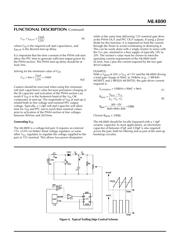
LEADING/TRAILING MODULATION
Conventional Pulse Width Modulation (PWM) techniques
employ trailing edge modulation in which the switch will
turn on right after the trailing edge of the system clock.
The error amplifier output voltage is then compared with
the modulating ramp. When the modulating ramp reaches
the level of the error amplifier output voltage, the switch
will be turned OFF. When the switch is ON, the inductor
current will ramp up. The effective duty cycle of the
trailing edge modulation is determined during the ON
time of the switch. Figure 4 shows a typical trailing edge
control scheme.
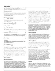
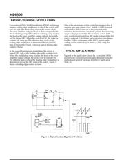
In the case of leading edge modulation, the switch is
turned OFF right at the leading edge of the system clock.
When the modulating ramp reaches the level of the error
amplifier output voltage, the switch will be turned ON.
The effective duty-cycle of the leading edge modulation is
determined during the OFF time of the switch. Figure 5
shows a leading edge control scheme.
One of the advantages of this control technique is that it
requires only one system clock. Switch 1 (SW1) turns off
and switch 2 (SW2) turns on at the same instant to
minimize the momentary “no-load” period, thus lowering
ripple voltage generated by the switching action. With
such synchronized switching, the ripple voltage of the first
stage is reduced. Calculation and evaluation have shown
that the 120Hz component of the PFC’s output ripple
voltage can be reduced by as much as 30% using this
method.
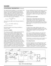
TYPICAL APPLICATIONS
Figure 6 is the application circuit for a complete 100W
power factor corrected power supply, designed using the
methods and general topology detailed in Application
Note 33.
REF
EA
–
+
–
+
OSC
DFF
R
D
Q
Q
CLK
U1
RAMP
CLK
U4
U3
C1
RL
I4
SW2
SW1
+
DC
I1
I2 I3
VIN
L1
VEAO
CMP
U2
RAMP
VEAO
TIME
VSW1
TIME
Figure 5. Typical Leading Edge Control Scheme
器件 Datasheet 文档搜索
AiEMA 数据库涵盖高达 72,405,303 个元件的数据手册,每天更新 5,000 多个 PDF 文件
