Datasheet 搜索 > 铝电解电容 > NIC > NRE-HW1R0M160V5X11TBSTF 数据手册 > NRE-HW1R0M160V5X11TBSTF 数据手册 1/3 页


¥ 0.218
NRE-HW1R0M160V5X11TBSTF 数据手册 - NIC
制造商:
NIC
分类:
铝电解电容
Pictures:
3D模型
符号图
焊盘图
引脚图
产品图
页面导航:
标记信息在P1
技术参数、封装参数在P1P2P3
应用领域在P2P3
型号编号列表在P1
导航目录
NRE-HW1R0M160V5X11TBSTF数据手册
Page:
of 3 Go
若手册格式错乱,请下载阅览PDF原文件
1
NIC COMPONENTS CORP. www.niccomp.com www.lowESR.com www.RFpassives.com www.SMTmagnetics.com
SPECIFICATIONS ARE SUBJECT TO CHANGE
Miniature Aluminum Electrolytic Capacitors
HIGH VOLTAGE, RADIAL, POLARIZED, EXTENDED TEMPERATURE
FEATURES
• HIGH VOLTAGE/TEMPERATURE (UP TO 450VDC/+105°C)
• NEW REDUCED SIZES
• MEETS THE REQUIREMENTS OF AEC-Q200*
*Contact NIC for supporting test data
NRE-HW Series
CHARACTERISTICS
Rated Voltage Range 160 ~ 450VDC
Capacitance Range 1.0 ~ 330µF
Operating Temperature Range
-40°C ~ +105°C (160 ~ 400V)
or -25°C ~ +105°C (450V)
Capacitance Tolerance ±20% (M)
Maximum Leakage Current @ 20°C CV ≤ 1000µF 0.03CV +15µA, CV > 1000µF 0.02CV +25µA (after 2 minutes)
Max. Tan δ @ 120Hz/20°C
W.V. 160 200 250 350 400 450
S.V. 200 250 300 400 450 500
Tan δ 0.20 0.20 0.20 0.25 0.25 0.25
Low Temperature Stability
Impedance Ratio @ 120Hz
Z-25°C/Z+20°C 3 3 3 4 6 6
Z-40°C/Z+20°C 6 6 6 8 10 -
Load Life Test at Rated W.V.
+105°C 2,000 Hours: 10φ & Up
+105°C 1,000 Hours: 8φ
Capacitance Change Within ±20% of initial measured value
Tan δ Less than 200% of specied maximum value
Leakage Current Less than specied maximum value
Shelf Life Test
+85°C 1,000 Hours with no load
Shall meet same requirements as in load life test
PRECAUTIONS
Please review the notes on correct use, safety and precautions found on
pages T10 & T11 of NIC’s Electrolytic Capacitor catalog.
Also found at www.niccomp.com/precautions
If in doubt or uncertainty, please review your specic application - process
details with NIC’s technical support personnel: tpmg@niccomp.com
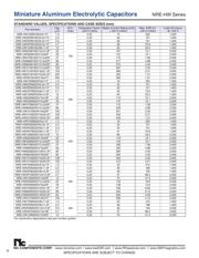
Cap
(µF)
Code
Working Voltage (Vdc)
160 200 250 350 400 450
1.0 1R0 5x11 5x11 5x11 6.3x11 - -
2.2 2R2 6.3x11 6.3x11 6.3x11 8x11.5 8x11.5 -
3.3 3R3 6.3x11 6.3x11 8x11.5 8x12.5 10x12.5 -
4.7 4R7 6.3x11 8x11.5 8x11.5 10x12.5 10x16 -
10 100 8x11.5 8x12.5 10x12.5 10x20 10x20 -
22 220 10x12.5 10x16 10x20 12.5x25 12.5x25 16x25
33 330 10x20 10x20 12.5x20 16x25 16x25 16x31.5
47 470 12.5x20 12.5x20 12.5x25 16x31.5 16x31.5 18x35.5
68 680 12.5x20 12.5x25 16x25 16x35.5 18x35.5 18x41
82 820 12.5x25 -
16x31.5
18x25
18x35.5 18x41 -
100 101 12.5x25 16x25 16x35.5 18x41 - -
150 151 16x31.5 16x35.5 18x35.5 - - -
220 221 16x35.5 18x35.5 - - - -
330 331 18x41 - - - - -
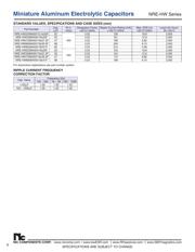
LEAD SPACING AND DIAMETER (mm)
β = L < 20mm = 1.5mm, L > 20mm = 2.0mm
Case Dia. (Dφ) 5 6.3 8 10 12.5 16 18
Lead Dia. (dφ) 0.5 0.5 0.6 0.6 0.6 0.8 0.8
Lead Spacing (F) 2.0 2.5 3.5 5.0 5.0 7.5 7.5
Dim α 0.5 0.5 0.5 0.5 0.5 0.5 0.5
STANDARD PRODUCT AND
CASE SIZE TABLE DφxL (mm)
*See Part Number System for Details
RoHS
Compliant
includes all homogeneous materials
PART NUMBER SYSTEM
NREHW 220 M 200V 10X16 TB Y F...
RoHS Compliant
TB = Tape & Box*
Case Size (DφxL)
Working Voltage (Vdc)
Tolerance Code (M=20%)
Capacitance Code: First 2 characters
signicant, third character is multiplier
Series
*see taping specications for details
Optional: For automotive equipment, sourced to special
production and inspection at TS-16949 certied production site
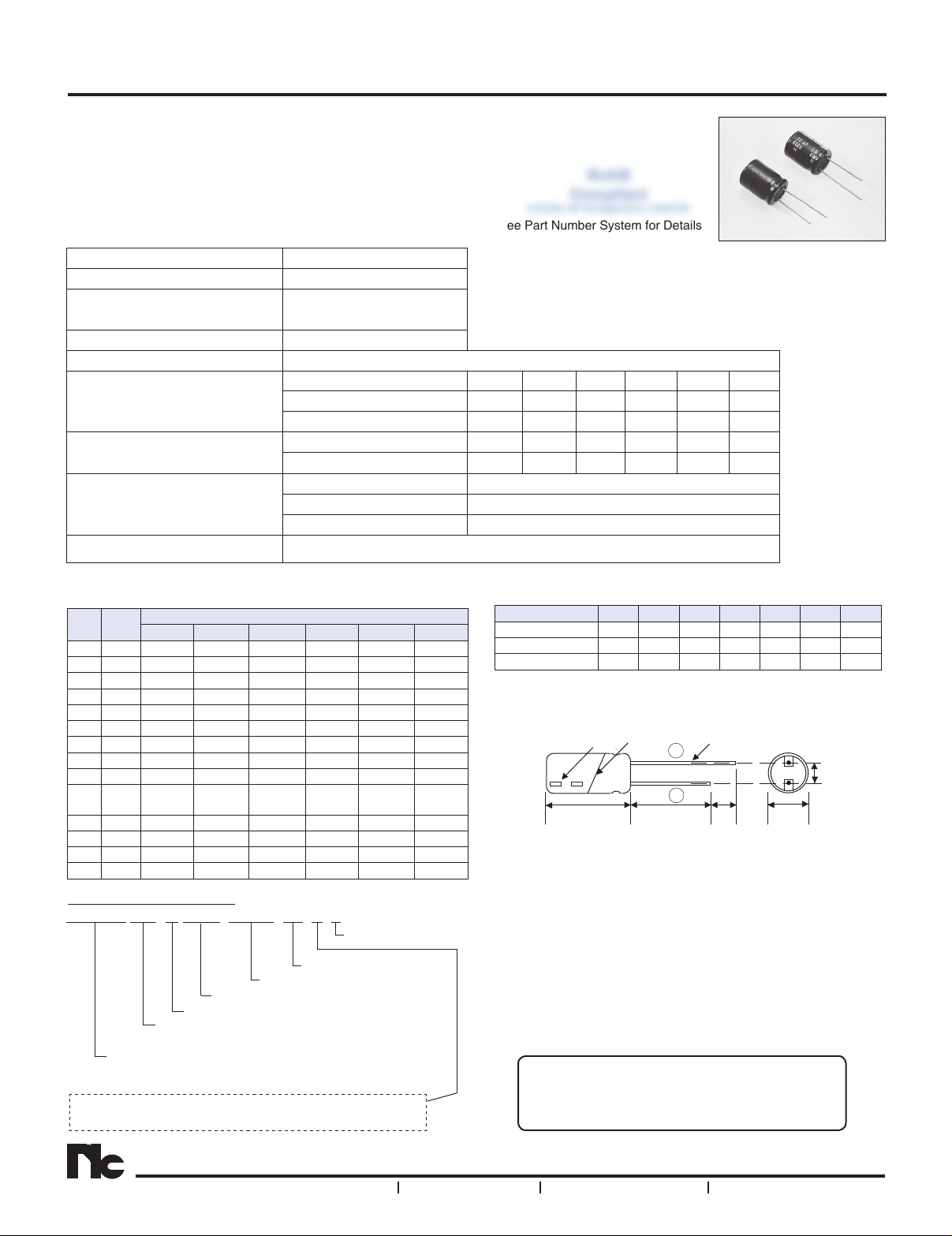
DIMENSIONS (mm)
dφ ± 0.05Sleeve
F ± 0.5
Dφ ± α
4mm
Min.
15mm Min. L + β max.
Polarity Marking
Drawing is representative of parts as supplied in bulk or
straight lead format, please see taping specication for details
on taped format packaging.
-
+
器件 Datasheet 文档搜索
AiEMA 数据库涵盖高达 72,405,303 个元件的数据手册,每天更新 5,000 多个 PDF 文件
