Datasheet 搜索 > 射频接收器 > Nordic Semiconductor > NRF24LE1-O17Q24-R7 数据手册 > NRF24LE1-O17Q24-R7 数据手册 18/190 页
 器件3D模型
¥ 22.542
NRF24LE1-O17Q24-R7 数据手册 - Nordic Semiconductor
制造商:
Nordic Semiconductor
分类:
射频接收器
封装:
QFN-24
Pictures:
3D模型
符号图
焊盘图
引脚图
产品图
页面导航:
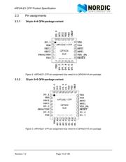
引脚图在P15P16P70P110P131P132P133Hot
典型应用电路图在P13
原理图在P14P18P56P71P81P94P98P100P112P115P116P119
封装尺寸在P180
型号编码规则在P188
标记信息在P188
功能描述在P1P12P18P57P71P82P90P95P98P105P112P116
技术参数、封装参数在P171
应用领域在P1
电气规格在P173P177


导航目录
NRF24LE1-O17Q24-R7数据手册
Page:
of 190 Go
若手册格式错乱,请下载阅览PDF原文件
Revision 1.2 Page 18 of 190
nRF24LE1 OTP Product Specification
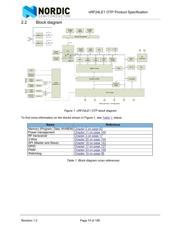
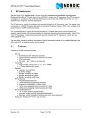
3.2 Block diagram
Figure 5. RF transceiver block diagram
3.3 Functional description
This section describes the different operating modes of the RF transceiver and the parameters used to
control it.
The RF transceiver module has a built-in state machine that controls the transitions between the different
operating modes. The state machine is controlled by SFR register RFCON and RF transceiver register
CONFIG, see section 3.5 for details.
3.3.1 Operational Modes
You can configure the RF transceiver to power down, standby, RX and TX mode. This section describes
these modes in detail.
3.3.1.1 State diagram
The state diagram (Figure 6.) shows the operating modes of the RF transceiver and how they function. At
the end of the reset sequence the RF transceiver enters Power Down mode. When the RF transceiver
enters Power Down mode the MCU can still control the module through the SPI and the rfcsn bit in the
RFCON register.
There are three types of distinct states highlighted in the state diagram:
• Recommended operating mode: is a recommended state used during normal operation.
• Possible operating mode: is a possible operating state, but is not used during normal operation.
• Transition state: is a time limited state used during start up of the oscillator and settling of the PLL.
器件 Datasheet 文档搜索
AiEMA 数据库涵盖高达 72,405,303 个元件的数据手册,每天更新 5,000 多个 PDF 文件
