Datasheet 搜索 > ON Semiconductor(安森美) > NSI45030AZ 数据手册 > NSI45030AZ 数据手册 1/7 页


¥ 0
NSI45030AZ 数据手册 - ON Semiconductor(安森美)
制造商:
ON Semiconductor(安森美)
Pictures:
3D模型
符号图
焊盘图
引脚图
产品图
页面导航:
导航目录
NSI45030AZ数据手册
Page:
of 7 Go
若手册格式错乱,请下载阅览PDF原文件
© Semiconductor Components Industries, LLC, 2011
October, 2011 − Rev. 2
1 Publication Order Number:
NSI45030AZ/D
NSI45030AZT1G
Constant Current Regulator
& LED Driver
45 V, 30 mA + 10%, 1.4 W Package
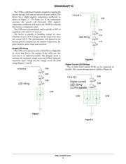
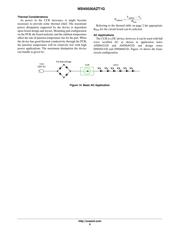
The linear constant current regulator (CCR) is a simple, economical
and robust device designed to provide a cost−effective solution for
regulating current in LEDs (similar to Constant Current Diode, CCD).
The CCR is based on Self-Biased Transistor (SBT) technology and
regulates current over a wide voltage range. It is designed with a
negative temperature coefficient to protect LEDs from thermal
runaway at extreme voltages and currents.
The CCR turns on immediately and is at 25% of regulation with
only 0.5 V Vak. It requires no external components allowing it to be
designed as a high or low−side regulator. The high anode-cathode
voltage rating withstands surges common in Automotive, Industrial
and Commercial Signage applications. The CCR comes in thermally
robust packages and is qualified to AEC-Q101 standard, and
UL94−V0 certified.
Features
• Robust Power Package: 1.4 Watts
• Wide Operating Voltage Range
• Immediate Turn-On
• Voltage Surge Suppressing − Protecting LEDs
• AEC-Q101 Qualified and PPAP Capable, UL94−V0 Certified
• SBT (Self−Biased Transistor) Technology
• Negative Temperature Coefficient
• These Devices are Pb−Free, Halogen Free/BFR Free and are RoHS
Compliant
Applications
• Automobile: Chevron Side Mirror Markers, Cluster, Display &
Instrument Backlighting, CHMSL, Map Light
• AC Lighting Panels, Display Signage, Decorative Lighting, Channel
Lettering
• Switch Contact Wetting
• Application Note AND8391/D − Power Dissipation Considerations
• Application Note AND8349/D − Automotive CHMSL
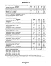
MAXIMUM RATINGS (T
A
= 25°C unless otherwise noted)
Rating
Symbol Value Unit
Anode−Cathode Voltage Vak Max 45 V
Reverse Voltage V
R
500 mV
Operating and Storage Junction
Temperature Range
T
J
, T
stg
−55 to +150 °C
ESD Rating: Human Body Model
Machine Model
ESD Class 1C
Class B
Stresses exceeding Maximum Ratings may damage the device. Maximum
Ratings are stress ratings only. Functional operation above the Recommended
Operating Conditions is not implied. Extended exposure to stresses above the
Recommended Operating Conditions may affect device reliability.
http://onsemi.com
SOT−223
CASE 318E
STYLE 2
MARKING DIAGRAM
Device Package Shipping
†
ORDERING INFORMATION
NSI45030AZT1G SOT−223
(Pb−Free)
1000/Tape & Reel
†For information on tape and reel specifications,
including part orientation and tape sizes, please
refer to our Tape and Reel Packaging Specifications
Brochure, BRD8011/D.
(Note: Microdot may be in either location)
Anode 1
Cathode 2/4
1
AYW
AAHG
G
A = Assembly Location
Y = Year
W = Work Week
AAH = Specific Device Code
G = Pb−Free Package
C
CANC
I
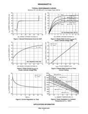
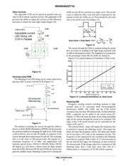
reg(SS)
= 30 mA
@ Vak = 7.5 V
器件 Datasheet 文档搜索
AiEMA 数据库涵盖高达 72,405,303 个元件的数据手册,每天更新 5,000 多个 PDF 文件
