Datasheet 搜索 > 运算放大器 > TI(德州仪器) > OP-07DPSR 数据手册 > OP-07DPSR 数据手册 5/21 页
 器件3D模型
¥ 10.605
OP-07DPSR 数据手册 - TI(德州仪器)
制造商:
TI(德州仪器)
分类:
运算放大器
封装:
SOIC-8
描述:
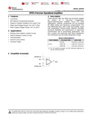
精密运算放大器器 PRECISION OPERATIONAL AMPLIFIERS
Pictures:
3D模型
符号图
焊盘图
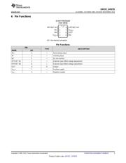
引脚图
产品图
页面导航:
引脚图在P3Hot
典型应用电路图在P8P9
原理图在P1P7P8P11
封装尺寸在P13P15P16
标记信息在P13P14
封装信息在P12P13P14P15P16
技术参数、封装参数在P4P10
应用领域在P1P21
电气规格在P5

导航目录
OP-07DPSR数据手册
Page:
of 21 Go
若手册格式错乱,请下载阅览PDF原文件
OP07C
,
OP07D
www.ti.com
SLOS099G –OCTOBER 1983–REVISED NOVEMBER 2014
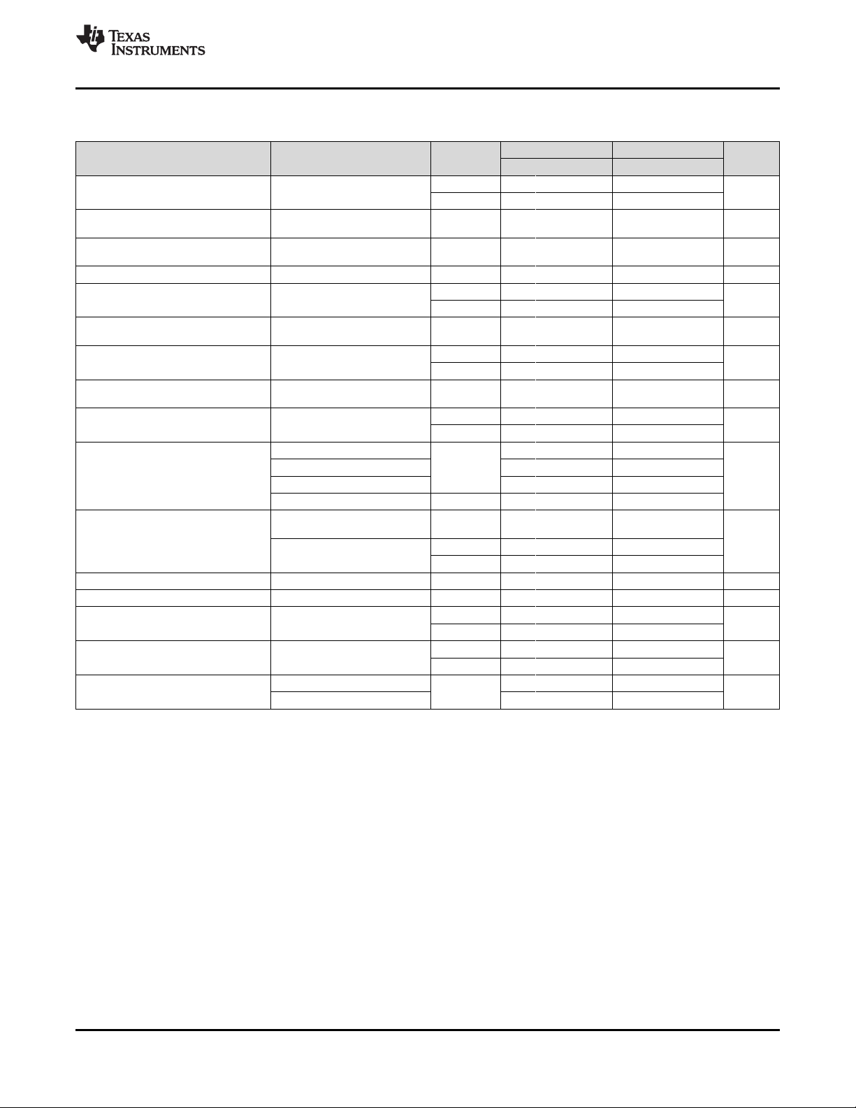
7.5 Electrical Characteristics
at specified free-air temperature, V
CC±
= ±15 V (unless otherwise noted)
(1)
OP07C OP07D
PARAMETER TEST CONDITIONS T
A
(2)
UNIT
MIN TYP MAX MIN TYP MAX
25°C 60 150
V
IO
Input offset voltage V
O
= 0 V R
S
= 50 Ω µV
0°C to 70°C 85 250
Temperature coefficient
α
VIO
V
O
= 0 V R
S
= 50 Ω 0°C to 70°C 0.5 2.5 µV/°C
of input offset voltage
Long-term drift of input
See 0.4 µV/mo
offset voltage
Offset adjustment range R
S
= 20 kΩ, See Figure 2 25°C ±4 mV
25°C 0.8 6
I
IO
Input offset current nA
0°C to 70°C 1.6 8
Temperature coefficient
α
IIO
0°C to 70°C 12 50 pA/°C
of input offset current
25°C ±1.8 ±12
I
IB
Input bias current nA
0°C to 70°C ±2.2 ±14
Temperature coefficient
α
IIB
0°C to 70°C 18 50 pA/°C
of input bias current
25°C ±13 ±14 ±13 ±14
Common-mode input
V
ICR
V
voltage range
0°C to 70°C ±13 ±13.5 ±13 ±13.5
R
L
≥ 10 kΩ ±12 ±13 ±12 ±13
R
L
≥ 2 kΩ 25°C ±11.5 ±12.8 ±11.5 ±12.8
V
OM
Peak output voltage V
R
L
≥ 1 kΩ ±12 ±12
R
L
≥ 2 kΩ 0°C to 70°C ±11 ±12.6 ±11 ±12.6
V
CC
= 15 V, V
O
= 1.4 V to 11.4 V,
25°C 100 400 400
R
L
≥ 500 kΩ
Large-signal differential
A
VD
V/mV
voltage amplification 25°C 120 400 120 400
V
O
= ±10, R
L
= 2 kΩ
0°C to 70°C 100 400 100 400
B
1
Unity-gain bandwidth 25°C 0.4 0.6 0.4 0.6 MHz
r
i
Input resistance 25°C 8 33 7 31 MΩ
25°C 100 120 94 110
Common-mode
CMRR V
IC
= ±13 V, R
S
= 50 Ω dB
rejection ratio
0°C to 70°C 97 120 94 106
25°C 7 32 7 32
Supply-voltage sensitivity
k
SVS
V
CC+
= ±3 V to ±18 V, R
S
= 50 Ω µV/V
(ΔV
IO
/ΔV
CC
)
0°C to 70°C 10 51 10 51
V
O
= 0, No load 80 150 80 150
P
D
Power dissipation 25°C mW
V
CC+
= ±3 V, V
O
= 0, No load 4 8 4 8
(1) Because long-term drift cannot be measured on the individual devices prior to shipment, this specification is not intended to be a
warranty. It is an engineering estimate of the averaged trend line of drift versus time over extended periods after the first 30 days of
operation.
(2) All characteristics are measured with zero common-mode input voltage, unless otherwise specified.
Copyright © 1983–2014, Texas Instruments Incorporated Submit Documentation Feedback 5
Product Folder Links: OP07C OP07D
器件 Datasheet 文档搜索
AiEMA 数据库涵盖高达 72,405,303 个元件的数据手册,每天更新 5,000 多个 PDF 文件
