Datasheet 搜索 > DA转换器 > TI(德州仪器) > PCM1702U/2K 数据手册 > PCM1702U/2K 数据手册 6/11 页
 器件3D模型
¥ 33.254
PCM1702U/2K 数据手册 - TI(德州仪器)
制造商:
TI(德州仪器)
分类:
DA转换器
封装:
SOIC-20
Pictures:
3D模型
符号图
焊盘图
引脚图
产品图
页面导航:
导航目录
PCM1702U/2K数据手册
Page:
of 11 Go
若手册格式错乱,请下载阅览PDF原文件
6
®
PCM1702
Level Linearity
Deviation from ideal versus actual signal level is sometimes
called “level linearity” in digital audio converter testing. See
the “–90dB Signal Spectrum” plot in the Typical Perfor-
mance Curves section for the power spectrum of a PCM1702
at a –90dB output level. (The “–90dB Signal” plot shows the
actual –90dB output of the DAC). The deviation from ideal
for PCM1702 at this signal level is typically less than
±0.3dB. For the “–110dB Signal” plot in the Typical Perfor-
mance Curves section, true 20-bit digital code is used to
generate a –110dB output signal.
This type of performance is possible only with the low-
noise, near-theoretical performance around bipolar zero of
the PCM1702 advanced sign magnitude.
A commonly tested digital audio parameter is the amount of
deviation from ideal of a 1kHz signal when its amplitude is
decreased form –60dB to –120dB. A digitally dithered input
signal is applied to reach effective output levels of
–120dB using only the available 16-bit code from a special
compact disk test input. See the “16-bit Level Linearity” plot
in the Typical Performance Curves section for the results of
a PCM1702 tested using this 16-bit dithered fade-to-noise
signal. Note the very small deviation from ideal as the signal
goes from –60dB to –100dB.
DC SPECIFICATION
Idle Channel SNR
Another appropriate specification for a digital audio con-
verter is idle channel signal-to-noise ratio (idle channel
SNR). This is the ratio of noise on the DAC output at bipolar
zero in relation to the full scale range of the DAC. To make
this measurement, the digital input is continuously fed the
code for bipolar zero, while the output of the DAC is band-
limited from 20Hz to 20kHz and an A-weighted filter is
applied. The idle channel SNR for the PCM1702 is typically
greater than 120dB, making it ideal for low-noise applica-
tions.
Monotonicity
Because of the unique advanced sign magnitude architecture
of the PCM1702, increasing values of digital input will
always result in increasing values of DAC output as the
signal moves away from bipolar zero in one-LSB steps (in
either direction). The “16-bit Monotonicity” plot in the
Typical Performance Curves section was generated using
16-bit digital code from a test compact disk. The test starts
with 10 periods of bipolar zero. Next are 10 periods of
alternating 1LSBs above and below zero, and then 10
periods of alternating 2LSBs above and below zero, and so
on until 10LSBs above and below zero are reached. The
signal pattern then begins again at bipolar zero.
With PCM1702, the low-noise steps are clearly defined and
increase in near-perfect proportion. This performance is
achieved without any external adjustments. By contrast,
sigma-delta (“Bit-stream”, “MASH”, or 1-bit DAC) archi-
tectures are too noisy to even see the first 3 or 4 bits change
(at 16 bits), other than by a change in the noise level.
Absolute Linearity
Even though absolute integral and differential linearity specs
are not given for the PCM1702, the extremely low THD+N
performance is typically indicative of 17-bit integral linearity
in the DAC. The relationship between THD+N and linearity,
however, is not such that an absolute linearity specification
for every individual output code can be guaranteed.
Offset, Gain, and Temperature Drift
Although the PCM1702 is primarily meant for use in dy-
namic applications, specifications are also given for more
traditional DC parameters such as gain error, bipolar zero
offset error, and temperature gain and offset drift.
DIGITAL INPUT
Timing Considerations
The PCM1702 accepts TTL compatible logic input levels.
The data format of the PCM1702 is binary two’s comple-
ment (BTC) with the most significant bit (MSB) being first
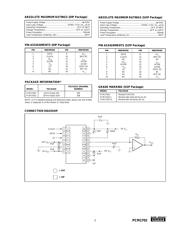
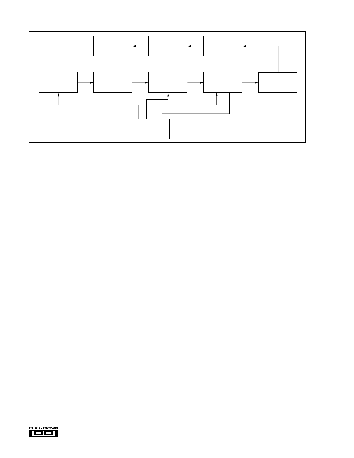
FIGURE 1. Production THD+N Test Setup.
Timing
Logic
Binary
Counter
Digital Code
(EPROM)
Parallel-to-Serial
Conversion
DUT
(PCM1702)
I to V
Converter
OPA627
Distortion
Analyzer
Programmable
Gain Amp
0dB to 60dB
Low-Pass Filter
40kHz 3rd Order
GIC Type
DATA
(Shiba Soku Model
725 or Equivalent)
Use 400Hz High-Pass
Filter and 30kHz
Low-Pass Filter
Meter Settings
Sampling Rate = 44.1kHz x 8(352.8kHz)
Output Frequency = 1002Hz
LE (Latch Enable)
CLOCK
器件 Datasheet 文档搜索
AiEMA 数据库涵盖高达 72,405,303 个元件的数据手册,每天更新 5,000 多个 PDF 文件
