Datasheet 搜索 > Banner > PD45VN6C100Q 数据手册 > PD45VN6C100Q 数据手册 3/8 页

¥ 0
PD45VN6C100Q 数据手册 - Banner
制造商:
Banner
Pictures:
3D模型
符号图
焊盘图
引脚图
产品图
页面导航:
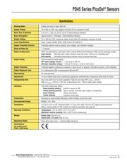
技术参数、封装参数在P5


导航目录
PD45VN6C100Q数据手册
Page:
of 8 Go
若手册格式错乱,请下载阅览PDF原文件
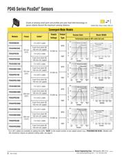
PD45 Series PicoDot
®
Sensors
P/N 115700
3
Banner Engineering Corp.
•
Minneapolis, MN U.S.A.
www.bannerengineering.com • Tel: 763.544.3164
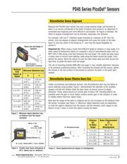
Retroreflective Sensor Alignment
Because the PicoDot laser sensor has such a long sensing range, and because its
beam is so narrow (compared to the beam of typical retro sensors), its alignment is
somewhat less forgiving and more difficult to accomplish. As Figure 3 indicates, the
effect of angular misalignment can be dramatic, especially over distance.
For example, with one 2 “ reflective target mounted at a distance of 20’ from the
sensor, only one degree of angular misalignment will cause the center of the laser
beam to miss the center of the target by 4”, and miss the target altogether by
almost 3”.
Alignment tip:
When using a small retroreflective target at medium or long range, it is
often useful to temporarily attach (or suspend) a strip of retroreflective tape (such as
BRT-THG-2-100) along a line that intersects the real target. The visible red laser beam
is easily seen in normal room lighting; sight along the beam toward the target, from
behind the sensor. Move the sensor to scan the laser beam back and forth across the
tape strip, to guide the beam onto the target.
The use of mounting bracket SMB-46A (see page 7) may simplify alignment, because
of its precision-positioning feature. After mounting the bracket and the sensor, tighten
the screws in the two corners of the bracket to position the beam in the exact spot
needed.
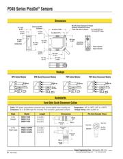
Retroreflective Sensor Effective Beam Size
Unlike conventional retroreflective sensors, the retroreflective laser has the ability to
sense relatively small profiles. Figure 1 demonstrates the diameter of the smallest
opaque rod that will reliably break the laser beam at several sensor-to-object
distances. These values assume an excess gain of about 10X. Flooding effects are
possible when the gain is much higher (reduce sensor gain in this situation in order
to reliably detect minimum object sizes).
Note that the shape of the beam is elliptical and its size increases as the distance from
the sensor increases (see Figure 1). Minimum object detection sizes are dependent
on both the object’s distance from the sensor, and the direction (with respect to the
beam’s X and Y axes) in which the object crosses the beam.
Y
Beam divergence
approximately 1 milliradian
X
Distance
from
Sensor to
Object
Minimum Detection size
X
Y
0.3 m (1')
1.78 mm
(0.07 ")
3.30 mm
(0.13")
1.5 m (5')
2.03 mm
(0.08 ")
4.06 mm
(0.16")
3 m (10')
3.05 mm
(0.12")
5.08 mm
(0.20 ")
9 m (30')
5.08 mm
(0.20 ")
8.13 mm
(0.32")
15 m (50')
9.65 mm
(0.38")
12.7 mm
(0.50")
18 m (60')
12.7 mm
(0.50")
19.05 mm
(0.75")
Ø = Misalignment Angle
Y = X(tan Ø)
X
Laser
Emitter
Y
Ø
Beam size and shape at
aperture
LASER LIGHT
DO NOT STARE INTO BEAM
CLASS 2 LASER PRODUCT
Avoid exposure - laser light
emitted from this aperture
PEAK POWER 2 mW
20KHz 10% DUTY CYCLE
660 - 680 nm
COMPLIES TO 21 CFR PART
1040.10 AND EN60825-1:1994
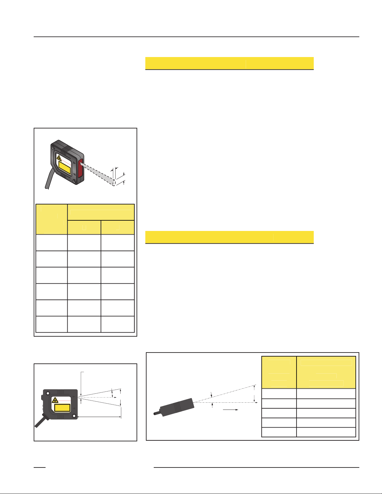
Sensing Distance = X
Approx.
0.5 m rad = 0.029˚
Approx. 2 mm
W = 2 mm + 2X(tan 0.029˚) = 2 mm + X(0.001)
W
Laser Emitter
Figure 2. PicoDot laser beam divergence at
25°C (beam size vs. distance)
Figure 1. Minimum object detection size,
as distance from the sensor
increases
Figure 3. Beam displacement per degree of misalignment
Distance
(X)
To Retro
Target
Beam Displacement
(Y)
for 1° of
Misalignment
1.5 m (5')
25 mm (1 ")
3 m (10')
50 mm (2")
6 m (20')
100 mm (4")
15 m (50')
250 mm (10")
30 m (100')
500 mm (20 ")
器件 Datasheet 文档搜索
AiEMA 数据库涵盖高达 72,405,303 个元件的数据手册,每天更新 5,000 多个 PDF 文件
