Datasheet 搜索 > 微控制器 > Microchip(微芯) > PIC12F1572-I/MF 数据手册 > PIC12F1572-I/MF 数据手册 123/334 页

 器件3D模型
¥ 14.204
PIC12F1572-I/MF 数据手册 - Microchip(微芯)
制造商:
Microchip(微芯)
分类:
微控制器
封装:
DFN-8
描述:
PIC 32MHz 闪存:2K@x14bit
Pictures:
3D模型
符号图
焊盘图
引脚图
产品图
页面导航:
引脚图在P3P10P11P119P204P243P244Hot
典型应用电路图在P127P244
原理图在P9P13P48P59P87P120P123P129P133P143P147P150
封装尺寸在P312
标记信息在P309P310P311
封装信息在P309P312P313P314P315P317P318P319P320P321P322P323
技术参数、封装参数在P52P54P72P84P85P88P130P136P141P149P150P156
应用领域在P44
电气规格在P52P54P72P84P85P88P130P136P141P149P150P156
导航目录
PIC12F1572-I/MF数据手册
Page:
of 334 Go
若手册格式错乱,请下载阅览PDF原文件
2013-2015 Microchip Technology Inc. DS40001723D-page 123
PIC12(L)F1571/2
13.0 FIXED VOLTAGE REFERENCE
(FVR)
The Fixed Voltage Reference (FVR) is a stable voltage
reference, independent of V
DD, with a nominal output
level (V
FVR) of 1.024V. The output of the FVR can be
configured to supply a reference voltage to the
following:
• ADC input channel
• Comparator positive input
• Comparator negative input
The FVR can be enabled by setting the FVREN bit of
the FVRCON register.
13.1 Independent Gain Amplifier
The output of the FVR supplied to the peripherals,
(listed above), is routed through a programmable gain
amplifier. Each amplifier can be programmed for a gain
of 1x, 2x or 4x, to produce the three possible voltage
levels.
The ADFVR<1:0> bits of the FVRCON register are
used to enable and configure the gain amplifier settings
for the reference supplied to the ADC module. Refer-
ence Section 15.0 “Analog-to-Digital Converter
(ADC) Module” for additional information.
The CDAFVR<1:0> bits of the FVRCON register are
used to enable and configure the gain amplifier settings
for the reference supplied to the comparator modules.
Reference Section 17.0 “Comparator Module” for
additional information.
To minimize current consumption when the FVR is
disabled, the FVR buffers should be turned off by
clearing the Buffer Gain Selection bits.
13.2 FVR Stabilization Period
The FVR can be enabled by setting the FVREN bit of
the FVRCON register.
When the Fixed Voltage Reference module is enabled, it
requires time for the reference and amplifier circuits to
stabilize. Once the circuits stabilize and are ready for use,
the FVRRDY bit of the FVRCON register will be set. See
the FVR Stabilization Period characterization graph,
Figure 27-21.
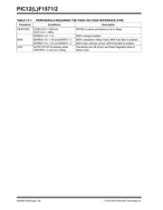
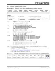
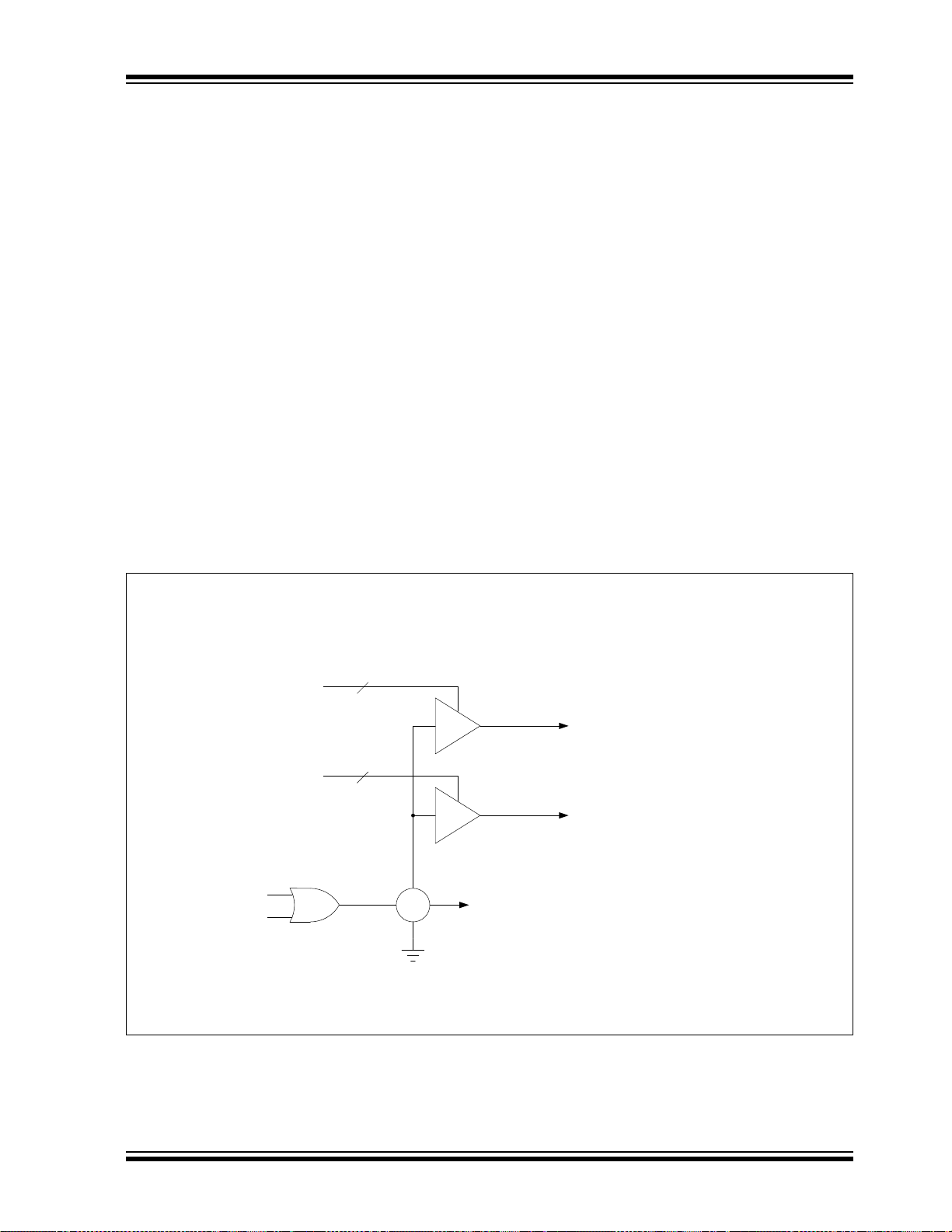
FIGURE 13-1: VOLTAGE REFERENCE BLOCK DIAGRAM
Note 1: Any peripheral requiring the Fixed Voltage Reference (see Table 13-1).
1x
2x
4x
1x
2x
4x
ADFVR<1:0>
CDAFVR<1:0>
FVR_buffer1
(To ADC Module)
FVR_buffer2
(To Comparators)
+
_
FVREN
FVRRDY
Note 1
2
2
Rev. 10-000053A
8/6/2013
器件 Datasheet 文档搜索
AiEMA 数据库涵盖高达 72,405,303 个元件的数据手册,每天更新 5,000 多个 PDF 文件
