Datasheet 搜索 > 微控制器 > Microchip(微芯) > PIC12F509-E/MS 数据手册 > PIC12F509-E/MS 数据手册 52/111 页
 器件3D模型
¥ 7.383
PIC12F509-E/MS 数据手册 - Microchip(微芯)
制造商:
Microchip(微芯)
分类:
微控制器
封装:
MSOP-8
描述:
PIC12 系列 41 B RAM 1.5 kB 闪存 8位 闪存 微控制器 - MSOP-8
Pictures:
3D模型
符号图
焊盘图
引脚图
产品图
页面导航:
引脚图在P4P13P15Hot
原理图在P12P14P35P39P50P53
标记信息在P91P92
封装信息在P91P101P102P109
功能描述在P7
技术参数、封装参数在P42P43P46P52P55
应用领域在P7
电气规格在P46P49

导航目录
PIC12F509-E/MS数据手册
Page:
of 111 Go
若手册格式错乱,请下载阅览PDF原文件

PIC12F508/509/16F505
DS41236E-page 52 © 2009 Microchip Technology Inc.
7.5 Device Reset Timer (DRT)
On the PIC12F508/509/16F505 devices, the DRT runs
any time the device is powered up. DRT runs from
Reset and varies based on oscillator selection and
Reset type (see Table 7-6).
The DRT operates on an internal RC oscillator. The
processor is kept in Reset as long as the DRT is active.
The DRT delay allows V
DD to rise above VDD min. and
for the oscillator to stabilize.
Oscillator circuits based on crystals or ceramic resona-
tors require a certain time after power-up to establish a
stable oscillation. The on-chip DRT keeps the devices in
a Reset condition for approximately 18 ms after MCLR
has reached a logic high (VIH MCLR) level.
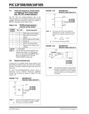
Programming (GP3/RB3)/MCLR
/VPP as MCLR and
using an external RC network connected to the MCLR
input is not required in most cases. This allows savings
in cost-sensitive and/or space restricted applications, as
well as allowing the use of the (GP3/RB3)/MCLR
/VPP
pin as a general purpose input.
The Device Reset Time delays will vary from chip-to-
chip due to V
DD, temperature and process variation.
See AC parameters for details.
The DRT will also be triggered upon a Watchdog Timer
time-out from Sleep. This is particularly important for
applications using the WDT to wake from Sleep mode
automatically.
Reset sources are POR, MCLR
, WDT time-out and
wake-up on pin change. See Section 7.9.2 “Wake-up
from Sleep”, Notes 1, 2 and 3.
7.6 Watchdog Timer (WDT)
The Watchdog Timer (WDT) is a free running on-chip
RC oscillator, which does not require any external
components. This RC oscillator is separate from the
external RC oscillator of the (GP5/RB5)/OSC1/CLKIN
pin and the internal 4 MHz oscillator. This means that
the WDT will run even if the main processor clock has
been stopped, for example, by execution of a SLEEP
instruction. During normal operation or Sleep, a WDT
Reset or wake-up Reset, generates a device Reset.
The TO
bit (STATUS<4>) will be cleared upon a
Watchdog Timer Reset.
The WDT can be permanently disabled by
programming the configuration WDTE as a ‘0’ (see
Section 7.1 “Configuration Bits”). Refer to the
PIC12F508/509/16F505 Programming Specifications
to determine how to access the Configuration Word.
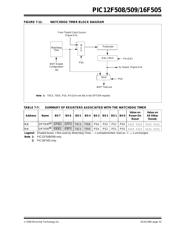
TABLE 7-6: DRT (DEVICE RESET TIMER
PERIOD)
7.6.1 WDT PERIOD
The WDT has a nominal time-out period of 18 ms, (with
no prescaler). If a longer time-out period is desired, a
prescaler with a division ratio of up to 1:128 can be
assigned to the WDT (under software control) by
writing to the OPTION register. Thus, a time-out period
of a nominal 2.3 seconds can be realized. These
periods vary with temperature, V
DD and part-to-part
process variations (see DC specs).
Under worst case conditions (V
DD = Min., Temperature
= Max., max. WDT prescaler), it may take several
seconds before a WDT time-out occurs.
7.6.2 WDT PROGRAMMING
CONSIDERATIONS
The CLRWDT instruction clears the WDT and the
postscaler, if assigned to the WDT, and prevents it from
timing out and generating a device Reset.
The SLEEP instruction resets the WDT and the post-
scaler, if assigned to the WDT. This gives the maximum
Sleep time before a WDT wake-up Reset.
Oscillator
Configuration
POR Reset
Subsequent
Resets
INTOSC, EXTRC 18 ms (typical) 10 μs (typical)
HS
(1)
, XT, LP 18 ms (typical) 18 ms (typical)
EC
(1)
18 ms (typical) 10 μs (typical)
Note 1: PIC16F505 only.
器件 Datasheet 文档搜索
AiEMA 数据库涵盖高达 72,405,303 个元件的数据手册,每天更新 5,000 多个 PDF 文件
